
Ruleset Overview
Rules are used to implement policy and invoke the flood control algorithms taken from the SUPER logic. Rules execute in the order specified by the user and are numbered according to priority. Rule #1 is the highest priority rule while the rule with the highest number (depends on the number of rules in the ruleset) is the lowest priority rule. In general, the lowest priority rules should execute first and represent the ideal operating conditions while the highest priority rules should execute last and represent special conditions or constraints that must be upheld. The idea behind rulesets meant to reproduce the SUPER logic is a bit different. Rulesets that implement SUPER flood control logic are designed to make mandatory releases first, then the releases may be increased as space allows. Therefore, the surcharge release rules execute first, then the rules to compute the regulation discharge and empty space, and finally the rules to compute the flood control releases. After the flood control model is working properly, additional higher priority rules could be added to account for other types of releases (for fish flows, power generation, irrigation demands, etc.).
Creating a New Ruleset
A new ruleset is created by selecting Policy, then Ruleset, then New in the main RiverWare menu. See RPL Set Editor View in RiverWare Policy Language (RPL) for details on the Ruleset Editor.
Agenda Order
To follow the guidelines presented in this document, the ruleset should execute the rules in order of lowest priority rules first and the highest priority rules last, that is rule n first, rule 1 last. This is the default structure but the following steps can be used to verify this.
1. Select View, then Show Advanced Properties menu in the RPL set editor.
2. In the Agenda Order field, select the toggle button for 3,2,1.
Order of Policies
In a rulebased simulation run, the run controller alternates between rule execution and object simulation. For a given controller timestep, all rules start out on the agenda. Rules are executed in reverse priority order until a rule succeeds and sets a slot in the model. Then control shifts to simulation and objects dispatch given the new information from the successful rule. When simulation is finished and there are no objects left to solve, control shifts back to the rule agenda and rules continue to execute until one is successful. Then control shifts back to simulation to simulate the affects of the rule. This process continues until there are no rules left on the agenda and no objects to solve. Then the controller moves to the next timestep and the process begins again.
Note: After a rule executes and is taken off the agenda it can go back on the agenda if one of its dependencies changes.
Note: Objects can solve at timesteps other than the current controller timestep if they have enough information to do so.
Table 3.1 shows the priority and execution order to be used by most USACE‑SWD models. The rules will execute from lowest priority to highest (8 to 1) as shown by the execution order. Descriptions of the rationale follow, sorted by execution order.
RPL Priority Order | Execution Order | Policy |
|---|---|---|
1 | 8 | Fish Releases (QFish) |
2 | 7 | Hydropower Release |
3 | 6 | Reservoir Diversions |
4 | 5 | Low-flow Releases |
5 | 4 | Flood Control |
6 | 3 | Regulation Discharge |
7 | 2 | Minimum Flood Control Releases (Optional) |
8 | 1 | Surcharge Release |
0. The forecast of incremental inflows from cumulative methods executes for each control point and reservoir object at the start of each timestep; see Forecasting Incremental Local Inflows From Cumulative Flows for details. This results in a new inflow forecast for each object. The computed inflow forecast sits on the Hydrologic Inflow Forecast slot on reservoir objects and on the Local Inflow slot on the control point objects. This is listed as step zero because it happens at the beginning of the timestep (and at priority 0) before any rules execute. Also at beginning of the run, the selected method in the Conditional Operating Level category will be executed; see Conditional Operating Levels in Objects and Methods for details. This could alter which operating level table will be used.
1. The lowest priority surcharge release rule is executed and it sets the surcharge release flag on the outflow slot of a reservoir object. That reservoir object then dispatch with the Solve given Inflow, Outflow dispatch method. While dispatching, the reservoir computes a surcharge release forecast. These values will be set on the Surcharge Release slot and on the Outflow slot. The reservoir object will then solve for storage and pool elevation over the forecast period using the new outflow values. When the reservoir is finished dispatching, the forecast outflows will be routed downstream to the next reservoir object. This is done by dispatching the reach and control point objects as they receive inflow values from upstream (their inflow values are the routed releases from the upstream reservoir). When all objects are finished dispatching, the next highest priority rule executes and sets the surcharge release flag on another reservoir object. That reservoir then dispatches and computes its surcharge release forecast. The forecasted outflow values are then routed downstream to the next reservoir. This process repeats until all surcharge release rules have executed, all reservoirs have computed a surcharge release forecast, and the surcharge releases have been routed downstream.
Note: The surcharge policy initializes the reservoir Outflow to zero if no surcharge release is necessary.
2. Optionally, minimum flood control releases can be made after the surcharge operation. These releases are considered minimums because they are made regardless of what the flood control logic computes. Also, the releases occupy downstream channel space so they should be made before the Regulation Discharge. It is up to the user to write the rule logic for when these should be made, but the rule should set the following:
– Reservoir.Flood Control Minimum Release
– Reservoir.Outflow
– Reservoir.Bypass or Regulated Spill (if this water should not go through the turbines or release structure)
See Flood Control Minimum Release for details.
3. The regulation discharge rule executes and sets the regulation discharge flag on the Reg Discharge Calculation slot on each control point object. This triggers each control point to dispatch. The control points compute the regulation discharge and empty space hydrographs over the forecast period. Because each control point has already computed its inflow forecast and the surcharge releases have already been routed from upstream reservoirs, the control point knows how much water is already occupying the channel at its location and can compute the empty space accordingly.
4. The flood control rule executes and calls the FloodControl predefined function. For all reservoirs in the computational subbasin and for all timesteps in the forecast period, the flood control releases are computed. The FloodControl function returns the final flood control releases and the final outflows (flood control release plus surcharge release) for the current timestep. The flood control rule sets the Outflow and Flood Control Release slots. This triggers each reservoir object to redispatch with the Solve given Inflow, Outflow method. The reservoirs compute their final storage and pool elevation values and the outflows are routed downstream.
5. The Low-flow Release rules execute next, releasing additional flows to meet downstream requirements. Flood control and low-flow releases are normally thought of as mutually exclusive for a particular reservoir in that when a flood control release is necessary, minimum flows downstream are satisfied and additional low-flow releases are not necessary. However, it is possible for some reservoirs to be in flood control while others are required to make low-flow releases. Also, in SUPER (hence in the RiverWare model), demands for diversions out of the rivers are satisfied by specifying low-flow requirements at control points upstream of the diversion points. Because these low flows are not restricted to environmental low flows, but also include diversion demands, it is possible that flood control releases are not adequate to satisfy these demands and additional releases are needed from the conservation pool. Hence the Low-flow Release rules execute regardless of whether flood control releases have been executed.
6. The Reservoir Diversion rules execute next, diverting water out of reservoirs directly to water users or to other reservoirs. This happens after the Low-flow rule executes, guaranteeing that the low flows will be satisfied at the possible expense of direct reservoir diversions. This is the expected behavior if the low flows are strictly environmental. However, the fact that the environmental and out-of-river diversions are grouped together means that the out-of-river diversions have priority over the out-of-reservoir diversions. If this relative priority is not desirable, the rules could be reversed and/or the out-of-river demands can be separated from low-flow demands that are strictly environmental.
7. The Hydropower rule executes last. All other releases automatically go through the turbines and generate power to the maximum extent possible, so when this rule fires, it compares the hydropower already being generated at each reservoir with the specified load. If the load is not met, the rule makes an additional release to generate additional power. These releases are constrained only by power pool drawdown limits and limitations on increasing flooding downstream.
8. The Fish Release rules (where defined) execute and determine the additional outflow to meet the Fish Release demand. The rule sets the reservoir Outflow and reservoir Off Peak Spill slots. This again causes the system to redispatch and solve. The rule also performs accounting actions to calculate and set the inflows and outflows to the fish account on the reservoir.
Direct from reach diversions are not included in the rule set because they are designed to take whatever water is available in the reach.
Execution Constraints to Execute Rule Once per Timestep
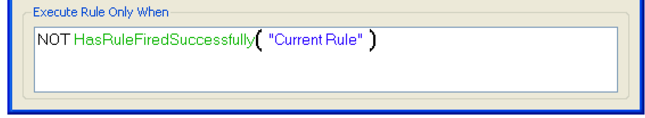
In general, each rule executes only once per timestep. This is guaranteed by including an execution constraint for each rule that calls the HasRuleFiredSuccessfully predefined function. For Example, as shown in Figure 3.1, the execution constraint for the Flood Control Rule says that it will only execute when NOT(HasRuleFiredSuccessfully(“Current Rule”)). The keyword “Current Rule” is used to reference the given rule. This prevents the user from having to change this argument if the name of the rule changes. The name of the rule, as a string, is also valid.
Figure 3.1 Execution constraint to limit firing
Types of Rules
In rulebased simulation, rules set slots equal to the value determined by the logic on the right side of the assignment statement. For the USACE‑SWD functionality, there are two variations to this: rules loop through a list of lists and set values from those two lists. Also, for Surcharge and regulation discharge, the rules set flags on slots. These two approaches are described in this section to familiarize the user with this structure.
Assigning Values Using Lists of Lists
The four specific USACE‑SWD predefined functions (FloodControl, HydropowerRelease, ComputeReservoirDiversions, MeetLowFlowRequirements) that are accessed by the rules all return a list of lists. The outer list contains an inner list that consists of a triplet of {slot, value, and object}. Example 3.1 illustrates.
Example 3.1
{ {“Res1.Outflow”, 6344.32 [“cfs”], “Res1”},
{“Res1.Flood Control Release”, 6344.32 [“cfs”], “res1”},
{“Res1.Target Balance Level”, 8.32, “res1”} ,
{“Res2.Outflow”, 3243.02 [“cfs”], “Res2”},
{“Res2.Flood Control Release”, 2312.20 [“cfs”], “Res2”},
{“Res2.Target Balance Level”, 8.32, “Res2”} }
Generally, the rule loops over this list and sets the slot at index 0 (the first one, the slot) to the value at index 1 (the second one, the value). The body of the rule would look as follows:
FOR (LIST triplet IN FloodControl( “Flood Basin” )) DO
( triplet < 0 > )[] = triplet < 1 >
END FOR
The third item, the object) is typically only used in debugging.
Setting Flags
The second unique syntax used by the USACE‑SWD is to set a flag on a slot. This applies to the Surcharge and Regulation discharge rules. In general, the slot is assigned the flag. The flags are all found on the palette. For example,
Reservoir.Outflow[ ] = SURCHARGE_RELEASE_FLAG
This assignment statement says that the Surcharge flag should be set on the Reservoir.Outflow slot at the current timestep.
Use of Computational Subbasin
A computational subbasin is a user configured subbasin that is used to specify a group of objects and the computations that should be performed on those objects.
Create a Computational Subbasin
The Subbasin Manager dialog is invoked by selecting Workspace, then Edit Subbasins from the main RiverWare menu. The Subbasin Manager dialog has three tabs: User Defined, Automatic, and Object Membership. Computational subbasins are added in the User-Defined Subbasins tab. Then, in the Subbasin Manager dialog, select Subbasin, then Append Typed Subbasin, then Computational. A new subbasin will appear in the dialog box and the user can rename the subbasin if desired. The subbasin will contain any objects that were selected on the workspace. The following section describes how to add objects to the subbasin.
Adding Objects to Subbasin
All objects which will be used in the specific calculations must be included in the computational subbasin. Furthermore, all objects in the subbasin must be continuous (i.e. there can be no disconnected objects with the exception of data objects). The easiest way to add objects to the subbasin is to select the objects on the RiverWare workspace by drawing a large box around all the relevant objects. This can be done by starting at a corner of the model then clicking and dragging until all the objects are highlighted. Once the objects are highlighted on the workspace, highlight the new subbasin then select Subbasin, then Append Members from Workspace in the Subbasin Manager dialog. The new subbasin should then show all of the objects associated with it when the subbasin view is expanded (by selecting the small icon to the left of the subbasin name). Even though data objects are not part of the flood control calculations, for ease of selecting and appending objects to a subbasin their inclusion in the flood control subbasin is allowed.
Revised: 01/04/2021