
User Interface
Object Dialogs
This document describes the user interface for the Object Viewer and Open Object dialog then presents a tool used to select methods on multiple objects. Additional information on display of objects on the workspace can be found as follows:
• Adding, selecting, and deleting objects. See “Objects on the Workspace”.
• Importing and exporting of objects and links. See “Importing and Exporting Objects”.
• Display groups allow you to change how objects are labeled, their layer and the color and line properties on the accounting workspace. See “Display Groups”.
• Clustering objects together into a single icon on the workspace. See “Object Clusters”.
The objects on the RiverWare workspace represent the physical layout of a modeled system. These objects contain the data and the physical process algorithms used in the simulation. To access the data and the methods (functions) which define the object, use the Object Viewer and/or the Open Object dialog.
Object Viewer and Open Object Dialogs
Open an object by double-clicking its object icon on the workspace or by selecting the name in the workspace object list. By default, the Object Viewer is shown with a tab for the Object. Figure 4.1 shows both an Object Viewer and Open Object dialog.
Figure 4.1
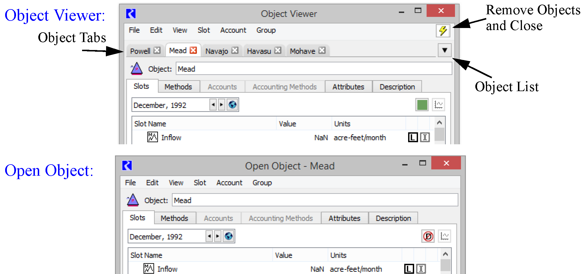
Note: The menu bar options will be the same. They are dynamically updated in the Viewer based on the object selected.
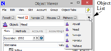
The Object Viewer is the default dialog used to look at an object. It is convenient as all objects open in the one dialog. Select the tabs to switch between objects. Or use the Object List menu on the right of the tabs. This is particularly useful if you have many objects in the viewer.
Arranging Tabs
There are three modes to arrange the object tabs in the viewer as selected in the Object Tabs menu:
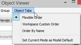
• Flexible Order: Tabs can be rearranged in any order. Drag the tabs left and right to rearrange them. New object tabs are appended to the right of existing tabs.
• Workspace Custom Ordering: Object tabs are ordered left to right using the custom object order from the workspace's Simulation Object list. See “Simulation Object List” for more information on the Simulation Object List.
• Order By Name: Object tabs are ordered left to right in case-insensitive lexical order.
Tip: A confirmation dialog is presented if you reorders the tab when not in Flexible Ordering mode. You have the choice to either cancel the move or switch to Flexible mode. You can still drag objects off and undock object in Workspace Custom or Order by Name mode.
In addition, in the Object Tabs menu, use the menu Set Current Mode as Model Default to set the current mode as the model default. This setting will be saved with the model file.
Undocking Objects
To look at two objects at once, drag the tab off the viewer to create an Open Object dialog for that object. Or use the File, then Undock Object menu or File Undock all Objects.
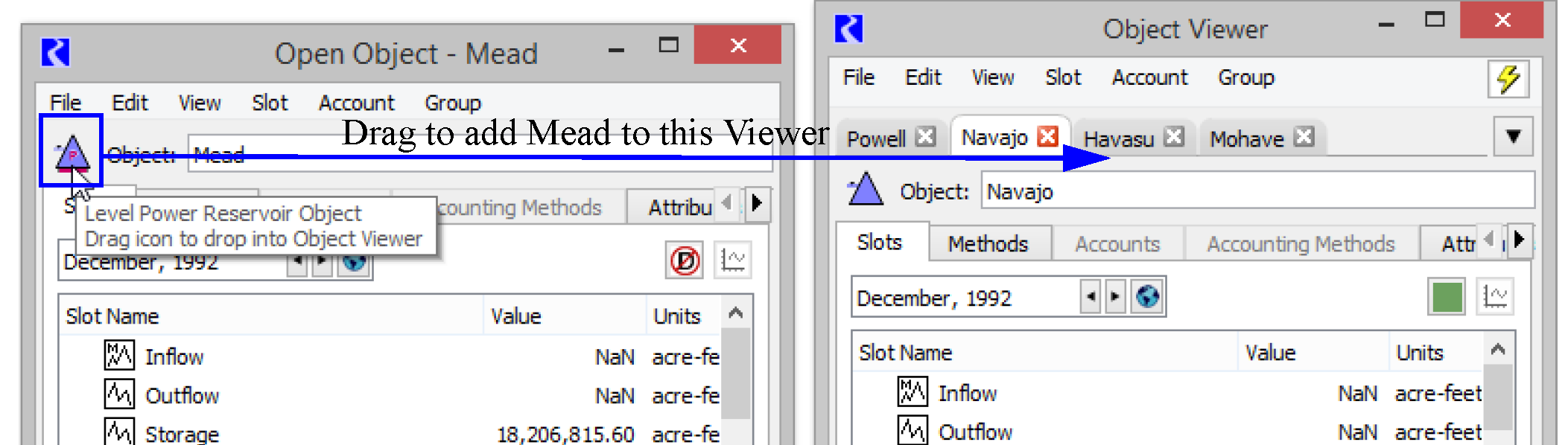
Redocking Objects
To move an Open Object dialog back onto the viewer, grab the Object icon and drag it anywhere onto the Viewer. A new tab will be created. Or use the File, then Dock In Object Viewer menu.
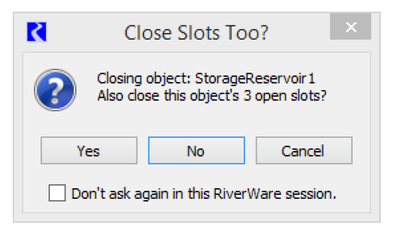
Closing an Object
Use the red X on the tab to close an object tab that is on the viewer. If you also have slots from that object shown in either the Slot Viewer or separate dialogs, you will be prompted with a confirmation asking if you want to close those slots too.
Closing the Viewer
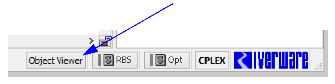
Select the red X on the viewer dialog to close the viewer. This will close the dialog, but all objects will remain in the viewer. Reopen the viewer and show the previously opened objects selecting the Object Viewer button in the lower right of the workspace.
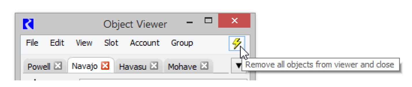
Select the Remove All Objects, yellow lightning bolt button to remove all objects from Viewer and close.
Using Object Dialogs
Regardless of whether you use the Object Viewer or individual Open Object dialog, the content is the same. All objects use the same format.
Figure 4.2
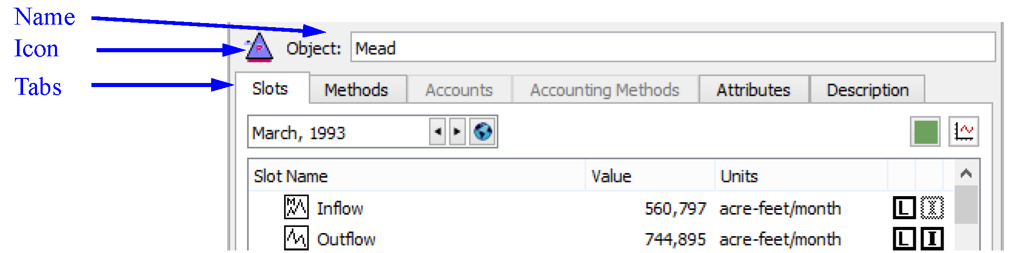
The dialog is organized by the following tabs:
• Slots: numerical model data
• Methods: user-selectable algorithms that represent physical and other processes
• Accounts (when enabled): containers to track water type or ownership
• Accounting Methods (when enabled): methods that correspond to water type or ownership
• Attributes: optional user defined attributes and values representing meta data for the object
• Description: optional text description of the object.
Naming an Object
You can change the name of any object by selecting the Object Name text field.
• User defined names may be any combination of letters, numbers, spaces and underscores, but no other characters. Names are case-sensitive and are not limited in length, but excessively long names will be displayed in their entirety, making the workspace visually cluttered.
Note: If you are renaming an object whose old name appears in RPL sets, a dialog asks if you want to search RPL sets for the old name and optionally replace occurrences with the new name. Entering Yes will bring up the RPL Search and Replace dialog with the results of a search for the old name in all RPL sets and with the new name filled into the Replace with field. You can examine the occurrences and choose to replace some or all of them with the new name.
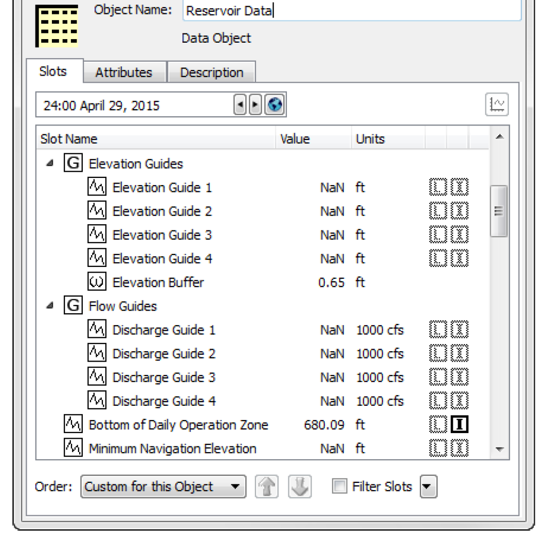
Slots Tab
The Slots tab contains information about each of the object’s slots. This information may include the slot Type, Value, and Status information.
The order of the slots is user configurable and can be saved with the model file; see “Sorting Slots” for details.
Figure 4.3
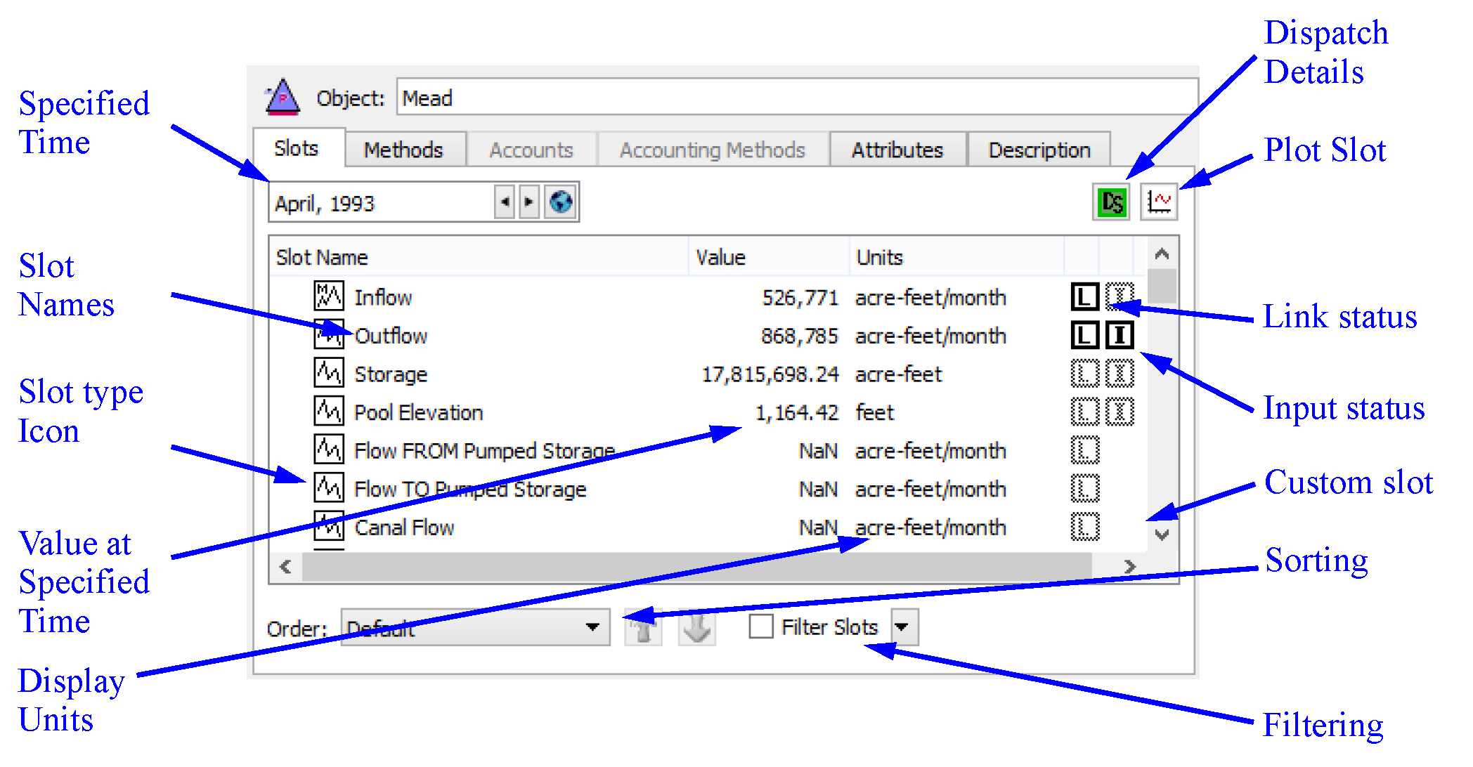
Slots Tab Tour
Following is a description of all of the pieces of the Slots tab.
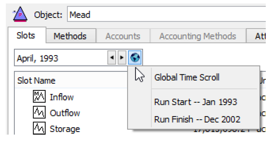
Specified Time
The DateTime spinner allows you to choose the date at which values are displayed in the slot list. The right arrow advances forward in time while the left arrow goes backward in time. Select the Globe icon and select Global Time Scroll to scroll all dialogs that reference a model timestep (E.g. slots, objects, plots, and model run analysis) to that date.
Slot Names
The names of simulations slots are predetermined and cannot be changed. Custom slots, which you can create on any object can be named as desired.
Slot Type Icons
Different types of slots are used for representing different types of data. The icons in the type column indicate the type of the slot. See “Types of Slots” for descriptions of the types of slots.
Slot Value
The Value field of the Slot List displays the value at the specified time in the slot. The value is displayed with the format selected by the user. When an object is first created, its values are all NaN (not-a-number).
Slot Units
The units shown are defined in the active Unit Scheme for that slot.
Dispatch Details
The Dispatch Details icon and button  displays the status of dispatching for the given object at the specified timestep (not including rule effects). Hover over the button to see a tooltip that summarizes the dispatch behavior. Select the button to open the model run analysis Dispatch Behavior Details for the given object; see “Dispatch Behavior Details Dialogs” in Debugging and Analysis for details. Shift-Click the button to show the Special Results Details; see “Model Run Analysis—Special Results Details Dialog” in USACE‑SWD Modeling Techniques for details.
displays the status of dispatching for the given object at the specified timestep (not including rule effects). Hover over the button to see a tooltip that summarizes the dispatch behavior. Select the button to open the model run analysis Dispatch Behavior Details for the given object; see “Dispatch Behavior Details Dialogs” in Debugging and Analysis for details. Shift-Click the button to show the Special Results Details; see “Model Run Analysis—Special Results Details Dialog” in USACE‑SWD Modeling Techniques for details. Plot Button
The Plot button  opens a plot dialog to display the values in the selected slots.
opens a plot dialog to display the values in the selected slots. Link Status
The Link Status indicator is bold when the slot is linked to another slot. Only timeseries slots may be linked; therefore, only timeseries slots display the Link Status.
Input Status
The Input Status indicator is bold when at the value at that timestep is flagged as an input. Only timeseries slots may have input flag; therefore, only timeseries slots display the Input Status.
Custom Slot indicator
The custom slot icon  is shown when the slot is custom (i.e. created by a user). Simulation slots do not have any icon in this column. In addition, custom slot icons have a pale yellow background.
is shown when the slot is custom (i.e. created by a user). Simulation slots do not have any icon in this column. In addition, custom slot icons have a pale yellow background. Sorting Slots
Following are the options for sorting and filtering slots.
Sorting Options
In the Slots tab, the following sorting orders are supported as shown in the Order menu at the bottom of the tab.
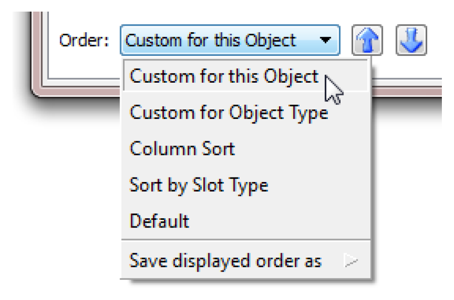
• Custom for this Object. Show a custom order for this object only. In this mode, the up and down arrows  are enabled and you can re-arrange slots. Select one or more slots, then select the arrows to move them up or down.
are enabled and you can re-arrange slots. Select one or more slots, then select the arrows to move them up or down.• Custom for this Object Type. Show the custom order defined for objects of this type, i.e. Storage Reservoir, Reach, Water User.
• Column Sort. Sort the slots alphabetically/numerically by column. In this mode, the column headers are enabled. Select any header to rearrange by that parameter. If you select a column header in any other mode, it will automatically switch to Column Sort order and then sort by that column.
• Sort by Slot Type. Group slots of the same type together and show Slot Groups together.
• Default. Use the internally defined slot order.
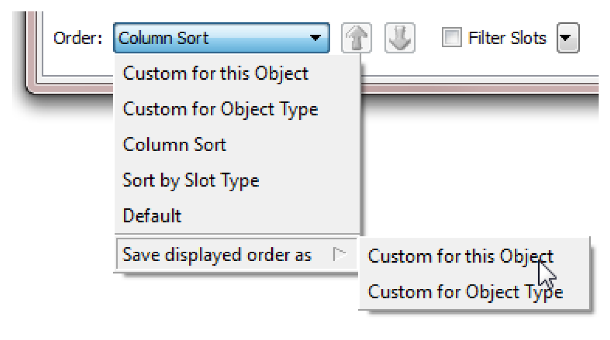
Saving the Order as Custom
There are two custom orders you can define and use, one for this object and one for objects of this type. You can only rearrange slots in the Custom for this Object mode. But you can save any order to either of these custom orders. At the bottom of the Order menu is a sub menu Save displayed order as. The options are as follows:
• Custom for this Object
• Custom for Object Type
When an object opens, it first tries to use the Custom for this Object order if defined, then the Custom for Object Type order if defined, and finally, it uses the Default order if neither of the other two are defined.
Filtering Slots
Like the sorting mechanism, filtering allows you to create a more meaningful view of the slots on the object. Filtering allows you to hide the slots you do not wish to see, perhaps because you are not using them. Filtering is controlled by two controls on the lower right part of the Slots tab, the check box and the menu.
The Filter Slots check box enables and disables the filtering. This immediately conveys whether some slots are hidden, and provides an easy way to temporarily show all slots without losing the configured show/hide states for the slots.
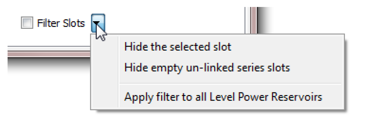
The Filter Slots menu defines how you wish to filter, as follows:
• Hide Selected Slots operation can be applied to the selected set of slots.
• Hide empty un-linked series slots will hide all series slots that do not have any values (i.e. NaNs only).
Once either of these options is chosen, the menu will say what is hidden and allow you to reveal all or some of the slots.
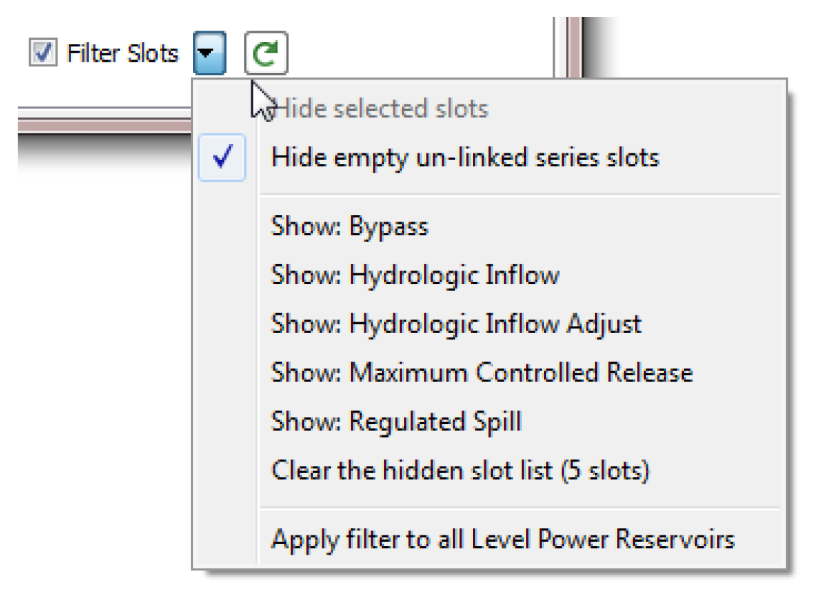
Use the Show: <slot> menu to reveal the slot. Use the Clear the hidden slot list menu to reveal all of these slots.
Select the Hide empty un-linked series slots to show these hidden slots.
Since this option depends on the values in the slots, there is a Refresh button to update the dialog. 
Finally, the Apply filter to All <objects> operation applies the filter settings to all objects of that type. This, along with the custom sort order described above, is a convenient way to make all objects of the same type appear the same.
Creating Custom Slots
The Slot menu and the right-click Add Slot menu has the following options to create custom slots:
• Add Series Slot
• Add Series Slot with Expression
• Add Integer Indexed Series Slots
• Add AggSeries Slot
• Add Integer Indexed AggSeries Slot
• Add Series Slot with Periodic Input
• Add Table Slot
• Add Statistical Table Slot
• Add Periodic Slot, Text Headers
• Add Periodic Slot, Numeric Headers
• Add Scalar Slot
• Add Scalar Slot with Expression
• Add Mass Balance Summary
• Add Time Aggregation Series Slot
Creating and Configuring Series Slots
Series slots are created through the Slot, then Add Series Slot menu. Custom Series slots on a Object can be linked to any linkable slot on the workspace. See “Series Slots” for details.
Creating and Configuring Table Slots
You can add a table slot of any dimension and units. See “Table Slots” for details.
Creating and Configuring Statistical Table Slots
Statistical table slots allow you to specify a statistical function, such as a flow duration curve, which is computed at the end of a run using the data in the slot(s). This statistical analysis data can then be plotted or exported to another application.
See “Statistical Table Slots” for details.
Creating and Configuring Periodic Slots
Periodic slots are used to represent data which repeats at regular time intervals. An example might be a set of evaporation coefficients for a reservoir. The rate of evaporation varies with such factors as temperature and wind speed, factors which vary seasonally. It is natural to assume that this variation is the same for each year. If this sort of data were entered into a series slot, then the same data would need to be repeated every year. This would be impractical and inconvenient for the user. On the other hand, if this data were entered in to a table slot, then the data would lose the time element associated with each value. This would make it difficult to look up or interpolate values with respect to time. The periodic slot meets the needs not met by these other slots.
You can create two different types of periodic slots, slots with text headers for the columns and slots with numeric headers for the columns.Select View, then Configure to configure the periodic slot. See “Periodic Slots” for details.
Creating Expression Slots
Expression slots are computational expressions that contain other slot names as variables. They are used to calculate quantities such as “combined Storage of all Reservoirs”, “weekly average Outflow of Hoover Dam”, or “the ratio of Hydrologic Inflow to Reach Inflow at selected structures”. To add a Series slot with expression, select Slot, then Add Series Slot with Expression. To add a Scalar slot with expression, select Slot, then Add Scalar Slot with Expression. See “Series Slots With Expression” for details.
Creating Mass Balance Summaries
The Mass Balance Summary slot is a user-defined hierarchy of series slot collections used to check (i.e. sum) mass balance across many objects. The collections are themselves series slots representing the sum of the contained slots. These slots can be used within RPL expressions and any other place where series slots are used. See “Mass Balance Summary Slots” for details.
Creating Time Aggregation Series Slots
Time Aggregation Series Slots temporally aggregate other series slot. See “Time Aggregation Series Slots” for details.
Slot Groups
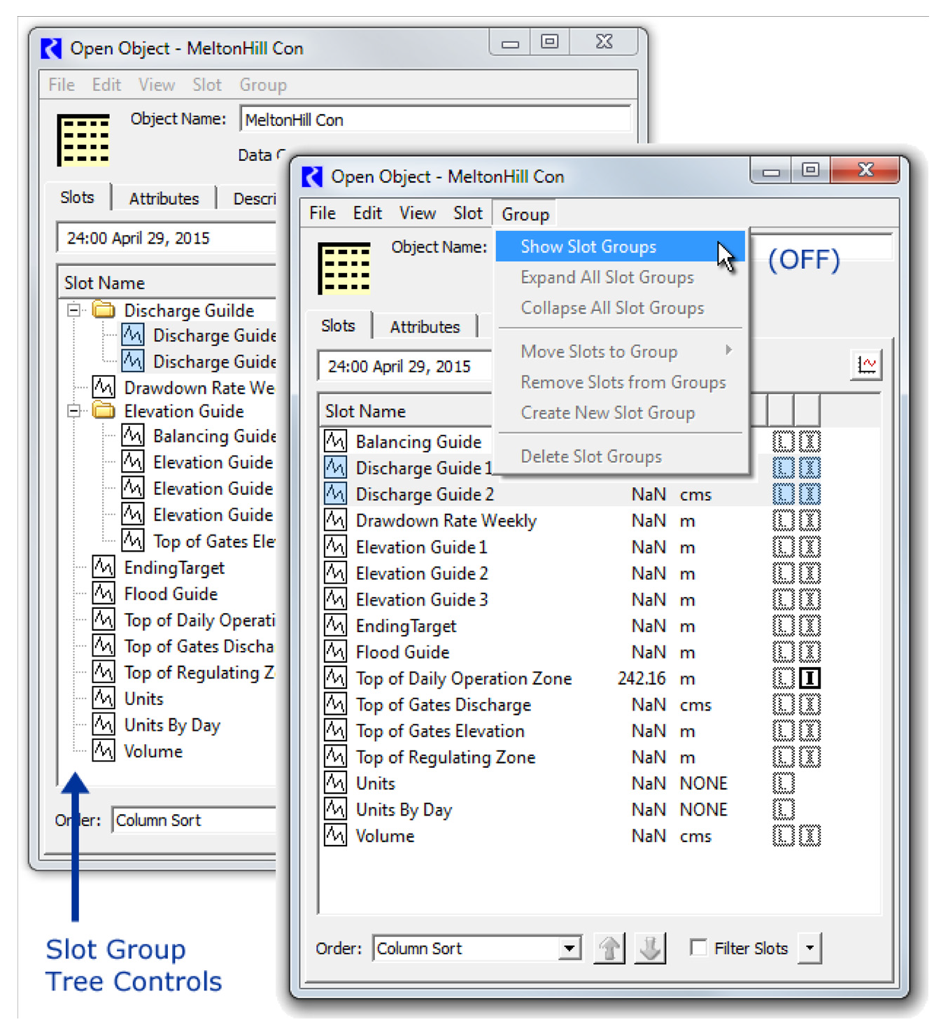
Slots (on non aggregate objects) can be grouped together within the Open Object dialog in named Slot Groups. Slot group items are indicated with a boxed [G] icon. Any slot can be in at most one slot group.
Figure 4.4
Slot groups do not change the relationship between a slot and its containing object -- the slot is still functionally, and internally, contained directly within the object. The complete name of the slot does not change when moving the slot into and out from a slot group. Slot names and slot group names on any particular object are unique. That is, no slot and slot group on a particular object can have the same name. Also, it is not possible for slots in distinct groups on the same object to have the same name.
Showing Slot Groups
Slot Groups can be shown or hidden as follows:
• Select Group, then Show Slot Groups.
• Right-click Show Slot Groups.
When the Show Slot Groups checkbox is cleared, slots are presented in the traditional way, as a single-level list of slot items.
Note: The state of this toggle is Global within the RiverWare session. Turning the Show Slot Groups checkbox on or off changes all Open Object dialogs for objects. This setting is saved in the RiverWare model file.
When Slot Groups are not shown, The tree ornamentation is hidden. Sorting of slots by name (e.g. after selecting the Slot Name column header) is done without regard to placement of slots within slot groups. Other operations in the Group menu are disabled.
Figure 4.5
When Slot Groups are shown, the Group, then Expand All Slot Groups and Group, then Collapse All Slot Groups menu items open or close all slot group tree items, respectively.
Note: When shown, Slot Groups are shown in the Slots tab according to the selected sorting Order presented at the bottom of the dialog. You can sort them alphabetically, by slot type and group, or through the custom sorting. See “Sorting Slots” for descriptions of these options.
Creating Slot Groups and Adding Slots
There are two ways to create a slot group:
1. Select one or more slots, then use the right-click context menu or the Group menu and choose Move Slots to Group, then New Slot Group. Then change the name of the new group as desired.
Figure 4.6
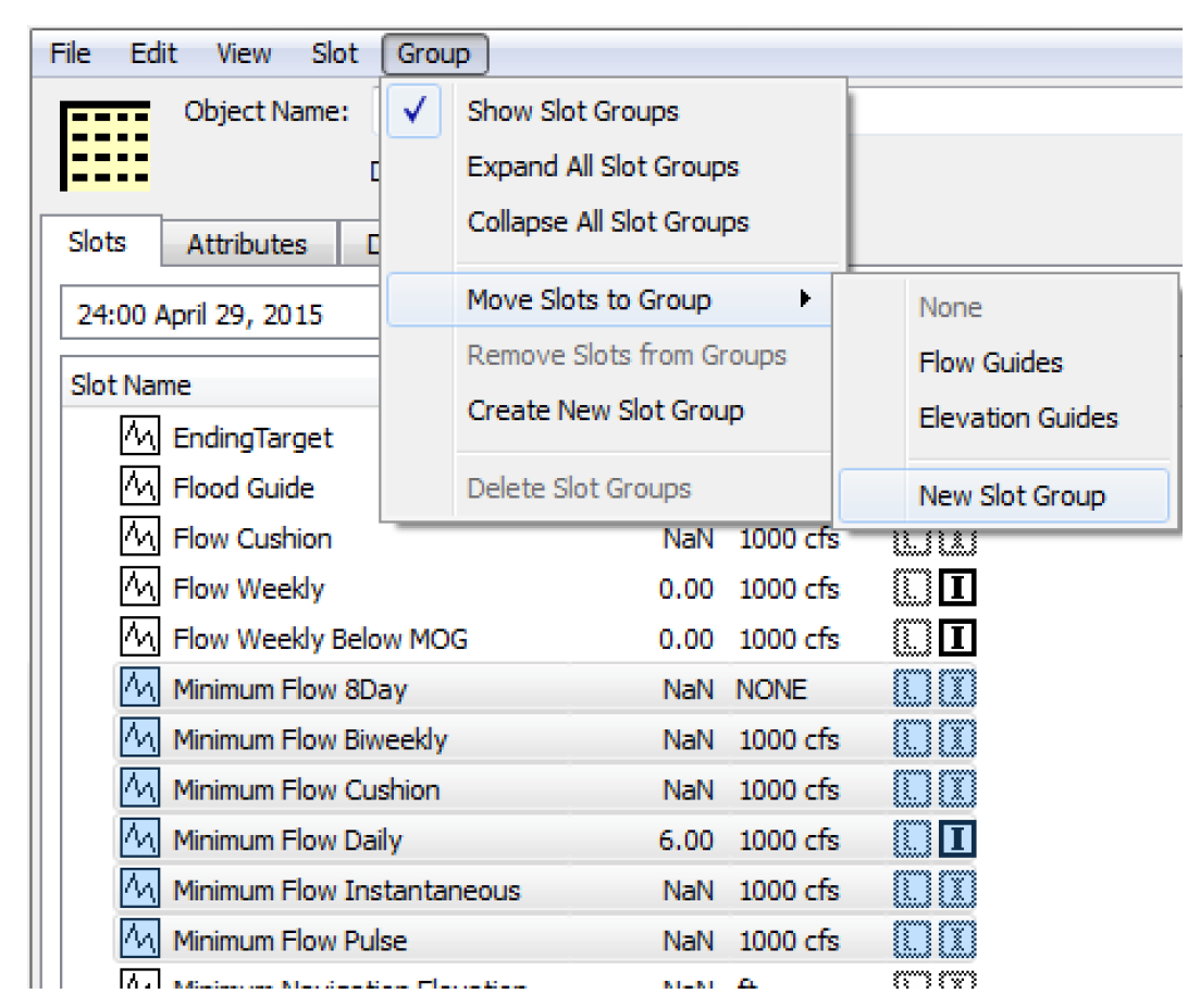
2. Use the Group, then Create New Slot Group menu. Then change the name of the new group as desired. Then select some slots and choose Move Slots to Group and choose the new group.
The new group name must be distinct from the names of all slots and other slot groups on the object, and cannot be None.
Removing Slots from a Group
There are two ways to remove a slot from a group:
1. Select the slot(s) to remove and use the right-click context menu or Group menu and select Remove Slots from Groups.
2. Select the slot(s) to remove and select Move Slots to Group, then None.
In both cases, the slot is removed from the group but continues to exist on the object.
Deleting Slot Groups and Slots
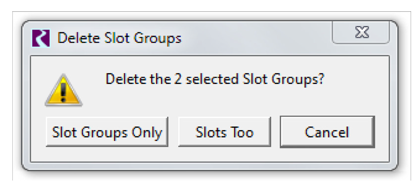
To remove or delete a Slot Group, select the group and choose Delete Slot Groups from either the right-click context menu or the Group menu. A confirmation dialog opens with the following choices:
• Slot Groups Only. Deletes only the group but not any slots.
• Slots Too. Delete the group and all slots within the selected groups.
• Cancel. Cancel the deletion operation.
Figure 4.7
Using Slot Groups
The following Slot menu operations also operate on slot groups, when selected.
Copy Slot Groups
The Copy Slot Groups operation copies the currently selected slot groups and containing slots to the system clipboard. Those slot groups them become available to be pasted within the same object, or in the Open Object dialog for a different object.
Paste Slot Groups
The Paste Slot Groups operation pastes the Slot Clipboard's slot groups into the object. If the object already has a slot group with the name of a slot group in the clipboard, then that existing slot group instance is used as the target for the paste operation -- i.e. that existing slot group will receive the slots from the analogous slot group in the clipboard. When pasting slots from a copied slot group, if slots having the same name already exist on the destination object, slightly differently named slots (copies) will be created from the copied slot group -- a distinct four-digit numeric number will be added to slot names, after having removed trailing digits, spaces, and underscore characters. After the paste operation, only the newly created slot groups and slots will be selected within the Open Object Dialog's slot list.
Duplicate Slot Groups
Whereas the Paste Slot Group operation always uses an existing slot group having the copied group's name, the Duplicate Slot Groups operation always creates new, slightly differently named, slot groups from the currently selected slot groups. It also copies the groups' slots, which are also given modified names.
Copy Slot Groups to Objects
This operation is a high-level copy operation; see “Copy Slots to Objects” for details.
Move Slot Groups to Object
See “Move Slots to Object” for a description of this option.
Copy and Paste Slots
Slots on any object (and slot groups) can be copied and then pasted to another object. With one or more slots selected, use the Slot, then Copy Slots (Ctrl-C) and Slot, then Paste Slots (Ctrl-V) menu to do this copy and paste action.
In addition, for a single object, you can use the Slot, then Duplicate Slots menu to create a duplicate of the slots, with slightly different names. The pasted custom slot name change consists of a different set of four digits at the end of the slot name. When modifying a slot name to insure uniqueness, all trailing digits, spaces, and underscores are first removed from the slot name, and an underscore and four digits are then appended.
Copy Slots to Objects
This section describes a high level utility that allows you to copy selected slots (and Slot Groups; see “Slot Groups”) and paste copies to multiple specified objects. This is particularly useful if you have consistent custom slots on simulation objects or data objects. For example, you may have 20 reservoirs and each has custom slots that contain policy or summary data. This utility allows you to configure or update one set of slots and then copy and paste the slots to all 20 reservoirs. Options are provided to specify to overwrite existing slots or add new slots.
To use the tool, select Slots (or Slot Groups) on the Open Object dialog Slots tab. Then, use the Slot, then Copy Slots to Objects menu. The Copy Slots to Objects dialog appears.
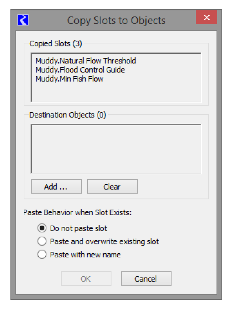
The upper portion shows the slots that will be copied. The middle box shows the Destination Objects.
Select the Add button to choose a set of Destination Objects, as shown in Figure 4.8.
Figure 4.8
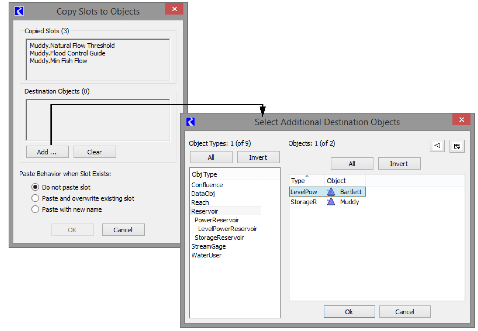
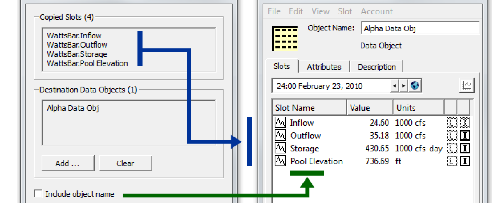
Select Clear to erase that list and start over. The Include object name check box is shown only when copying slots from a simulation object (e.g. a from a Reservoir). For the conventional Paste Slots operation, slots which were copied from a simulation object, the newly created (pasted) slots have names starting with the original simulation object's name. But when slots had been instead copied from a Data Object, the name of that data object is not pre-pended to the new slots' names. Selecting Include Object Name allows modification of the behavior of the Paste Slots operation.
Figure 4.9
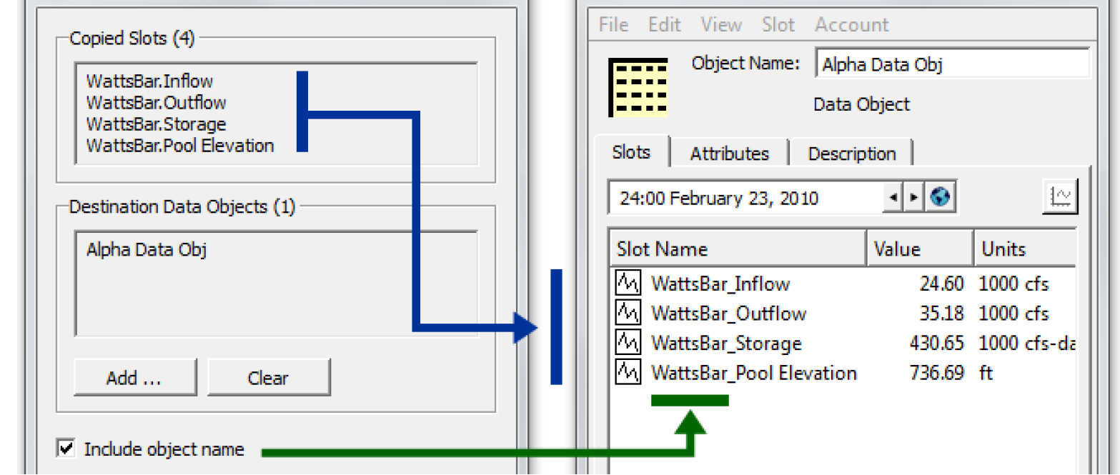
Figure 4.10
The lower part of the dialog lets you choose what to do when a slot of the same name exists on the destination object. The Paste Behavior when Slot Exists buttons control the behavior when a destination object already has a slot with the name of the copied slot (taking into account the Include Object Name option described above). It supports the following options:
• Do not paste slot. Leave existing matching slot on destination object intact.
• Paste and overwrite existing slot. Replace existing matching slot on destination object with copied slot.
• Paste with new name. Add a new copy of slot to the destination object with a new slot name.
Selecting OK performs the Copy Slots to Objects operation, as configured within the dialog. This shows a popup dialog indicating the result of the operation.
Note: Simulation slots cannot be overwritten.
Move Slots to Object
This section describes a utility that allows you to move selected custom slots (and Slot Groups; see “Slot Groups”) to a specified object. The move operation will cut the original slots and paste it to the new object.This is particularly useful to move custom slots from a data object to a simulation object.
Figure 4.11
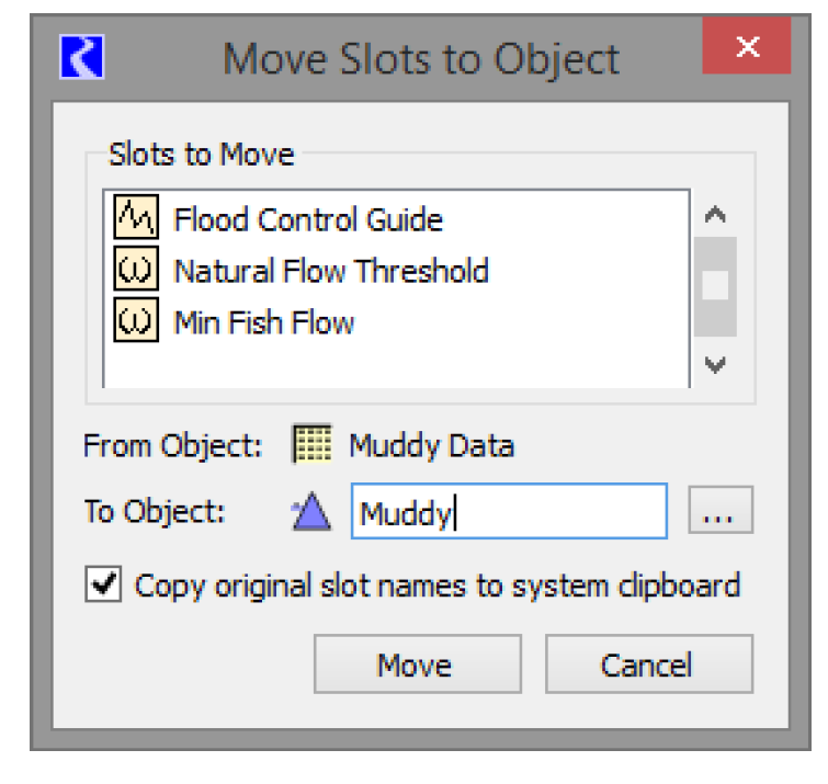
To use the tool, select one or more custom slots (or Slot Groups) on the Open Object dialog Slots tab. Then, use the Slot, then Move Slots to Object menu. The dialog to the right opens.
The upper portion shows a list of the slots that will be moved. The middle area shows the From Object and the To Object.
Select the Chooser button  to choose a single destination object.
to choose a single destination object.The Copy original slot names to system clipboard checkbox indicates whether the list of slot names (i.e. Object.Slot) is copied to the System Clipboard.
When ready, select the Move button. A confirmation dialog is presented. Once confirmed, the cut and paste sequence is performed and then the destination object’s dialog is shown with the slots selected.
If the slot name already exists on the destination object, the move operation is aborted and no slots are moved (none are created and none are deleted).
Note: When you move slots from one object to another, references to the slot on the original object may be broken. For example, RPL sets, DMIs, Scripts, and Model Reports may need to be modified. There is currently no automatic support to update the slot reference but the slot names can be copied to the system clipboard and you can use that as a guide. Search for each of the slots in the respective utilities and update accordingly.
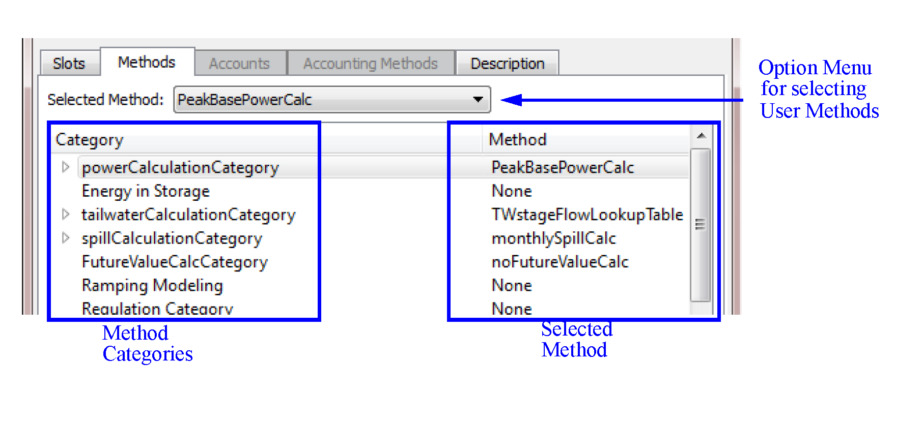
Methods Tab
User Methods allow each object’s physical process calculations to be customized. User Method Categories are defined for calculations such as evaporation, bank storage, power generation, spill, routing, tailwater and canal flow. Each Method Category contains one or more User Methods. For example, the Power Calculation Category contains many different methods for calculating Power. Some of these are general methods, designed for a variety of users. Others have been developed using custom calculations to meet the needs of particular groups, such as the LCR Power method which is used on the Lower Colorado Daily model.
The Methods display contains a scrollable list of Method Categories on the left and the corresponding selected User Method for each category on the right.
Figure 4.12
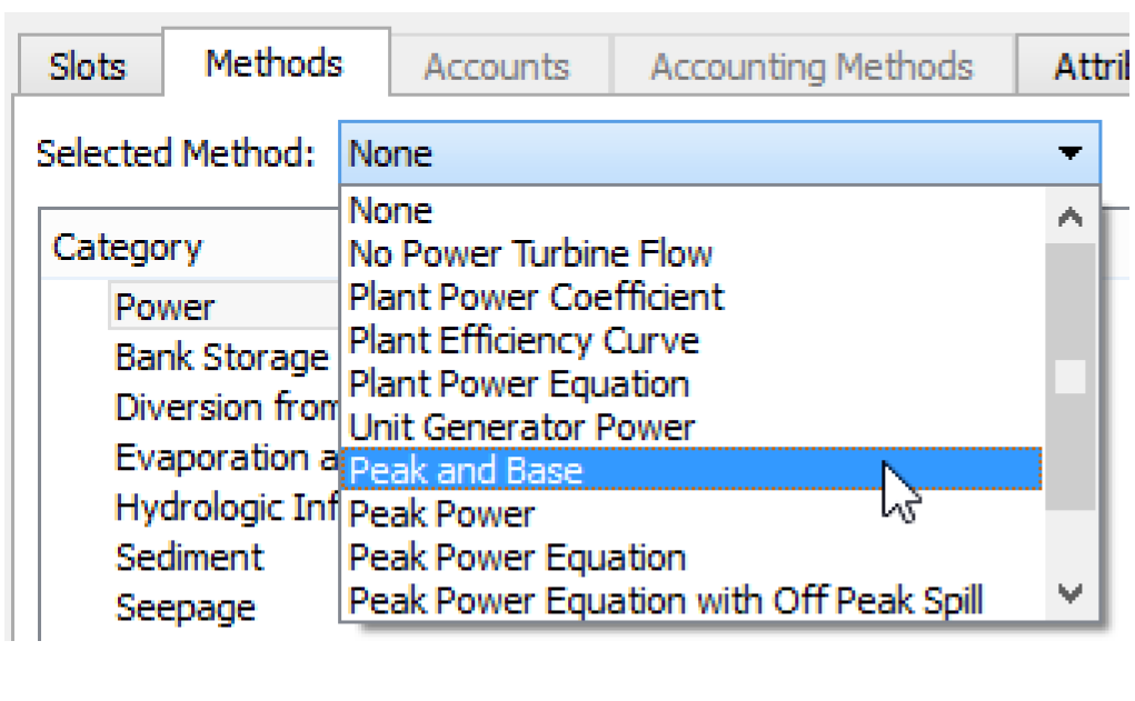
Selecting Methods
Objects are configured to represent the features in your basin using methods. These are selected from the Methods tab of the Open Object dialog. All of the user methods available within a Category can be viewed by selecting the Category and selecting the Selected Method pull down menu.
Figure 4.13
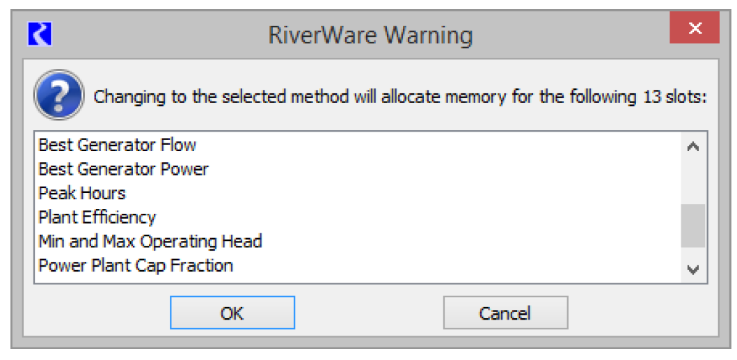
Memory Allocation for Method-specific Slots
Many user methods have special data needs beyond the general data needs of the object. In order to keep the size of the model in memory to a minimum, memory is allocated only for slots which are needed; i.e., general slots required by the object or slots associated with the Methods which have been selected. For example, all reservoirs need Inflow, Outflow and Storage slots. However, the list of slots associated with hydropower generation depends on which User Method is selected in the Power category.
To avoid allocating memory unnecessarily, the default User Method for all categories is an default method which has no slots and performs no calculations. Sometimes the empty default method is not a valid choice; you must select another method for simulation to proceed normally. For some categories, the empty method is a valid choice.
Figure 4.14
Method Dependencies
Some categories and user methods are not always available, as their availability depends on the other user methods that have been selected. For example, available user methods in the Power Release category depend on which method is selected in the Power category.
Selecting Methods on Multiple Objects
To select the same method on multiple objects, use the Multiple Object Method Selector by right-clicking a category and selecting Show in the Multiple Object Method Selector. See “Multiple Object Method Selector” for details on using the selector.
Accounts Tab
When Accounting is enabled, the Accounts display contains a scrollable list of Accounts that reside on the object. To switch to the Accounts view, select the Accounts tab or select View, then Accounts. The display of the main portion of the dialog changes to the Accounts view. See “Accounting Network” in Accounting for a description of the Accounts view.
Accounting Methods Tab
When accounting is enabled and an accounting controller is selected, the Accounting Methods tab is added to the Open Object dialog. It displays the following which can then be changed by the user:
• Available categories
• Selected method for each category
• Execution time
See “Selecting OLAMs and Execution Time” in Accounting for details on this tab.
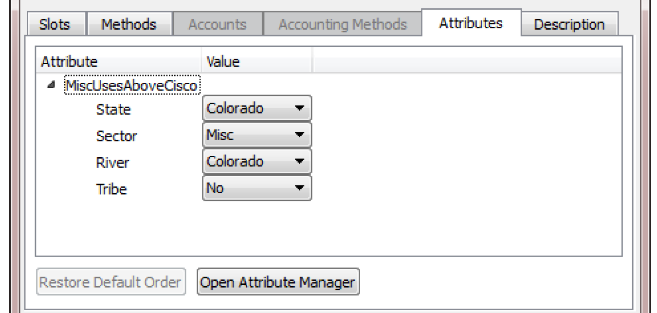
Attributes Tab
The Open Object dialog displays attributes and values on the Attributes tab. The tab has one row per Attribute defined for that type of object.
Figure 4.15
Attributes are defined in the Object Attribute Manager; see “Object Attributes Manager” for details.
Use one of the following methods to open the Object Attribute Manager:
• The Open Attribute Manager button,
• View, then Object Attributes Manager menu, or
• Right-click context menu to open the Object Attributes Manager.
The row lists the Attribute name and the value. A menu on the row allows you to select a different value for that attribute. No apply is necessary. To modify or view attributes on many objects, use the Edit Attributes on Objects menu; see “Edit Attributes on Objects” for details. Use the View, then Edit Attributes on Objects menu (or right-click context menu) to open that dialog.
Description Tab
The Description tab allows you to enter a description of the object. Select the Description tab to open the description area.
Figure 4.16
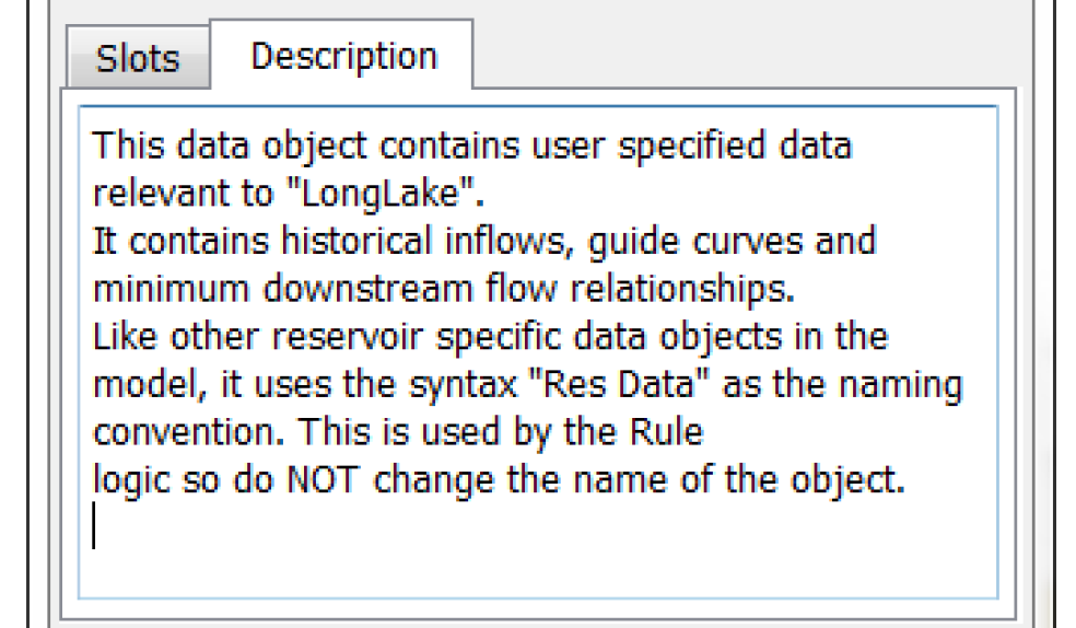
The normal cut, copy, paste (to the system clipboard) are available.
You can also enter a description of each slot on the object. See “Slot Descriptions” for details.
Aggregate Objects
RiverWare has three types of aggregate object (AggObjects): t
• Aggregate Reach (AggReach), which contains one or more element Reach objects
• Aggregate Diversion Site (AggDiversionSite), which contains zero or more element Water User objects
• Aggregate Distribution Canal (AggDistributionCanal), which contains one or more element Distribution Canal objects.
The aggregate object manages the linking structure of its elements and may also manage the solution methods for the elements. The AggDiversionSite has object solution methods independent of the behavior of its elements and may, therefore, stand alone.
AggObject Dialogs
The Open Object dialog for the AggObjects contains tree-views for both the Slots and Methods displays, where element objects are added and accessed. Also, the main menu bar has two additional items, Elements and Link Structure (the Link Structure item is not available for AggReaches or AggDistributionCanals). The first item listed is always the Aggregate Object itself. The remaining items (below the Aggregate Object) are the elements.
Figure 4.17
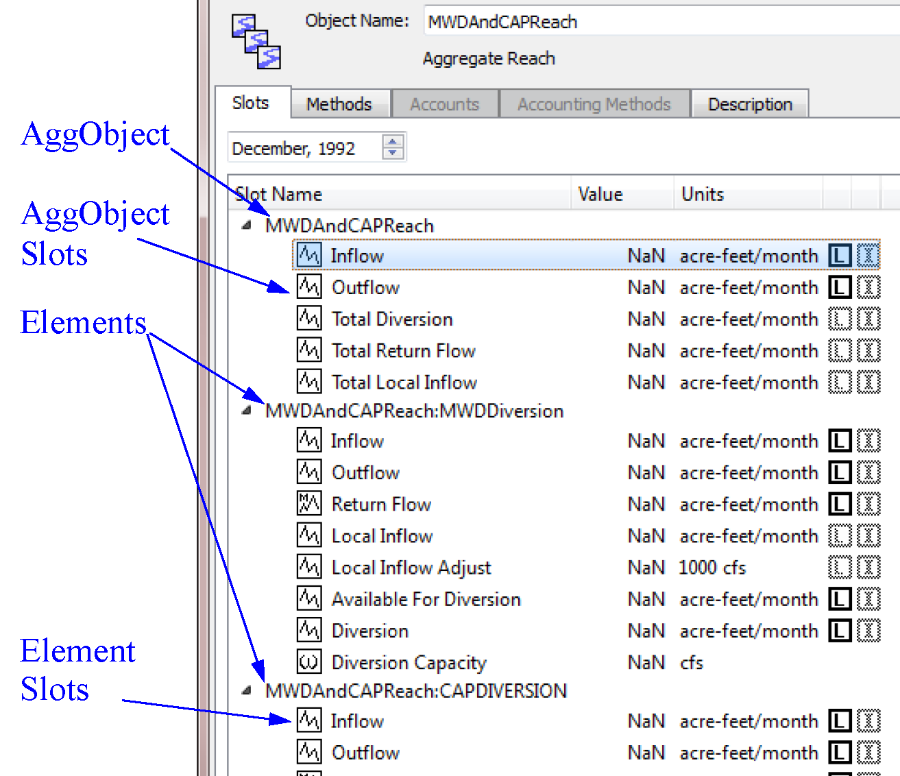
Viewing Element Slots and Methods
The slots or methods specific to the element objects are viewed in the lower portion of the Open Object dialog by selecting the tree-view triangle to the left of the element name. If the Open Object dialog is in the Slots display, the tree-view shows the slots associated with the elements. If Methods is selected, the tree-view shows the method categories for the elements, if any exist.
Note: Slot groups are not allowed on aggregate objects.
Object Attributes
Object Attributes are user defined Object meta data that allow you to define an Attribute for one or more types of objects. You then define values and assign those value to specific objects. For example, you might have 300 water users in your system. With this functionality, you can define, for example, a “Use” attribute and a “Jurisdiction” attribute. Then you can specify for each water user, its Use, i.e. Municipal, Industrial, or Agricultural, and its Jurisdiction, i.e. “Local”, “State”, “Federal”, etc. Each Attribute and Value is user defined and customized, both the text that you use and which objects types and specific objects to which they apply.
You can use attributes and values in user defined RPL expression and data analysis. For example, you could write an expression that sums up all diversions that represent the Municipal, Local uses. Or compute all depletions by a particular State.
Following is a bulleted list of features of attributes:
• There can be many attributes defined in a model, each has one or more possible values. A particular object can have zero or more attributes, but for each attribute, only ONE value is possible.
• An Attribute can be specific to one or more classes of objects (reach, water user, storage reservoir) including all objects.
• Attributes and values are strings.
• Attributes and Values are defined in the Attribute Manager.
• Values can be assigned from either the Edit Attributes on Objects or the Open Object dialog.
• Attributes and values are displayed on the Open Object dialog.
• Attributes and values accessible from RPL.
• The Selector dialogs have a filter to assist with selecting objects: Has Attribute Value.
• You can export/import the attributes and values from one RiverWare model to another.
This document discusses the Object Attribute Manager and Edit Attributes on Objects dialogs.
Object Attributes Manager
The Object Attributes Manager is accessible from each Open Object dialog and from the Workspace, then Objects, then Object Attributes Manager menu. The purpose of this dialog is creating, deleting, and otherwise managing attributes and their values. The function of applying values to multiple objects is provided by the Edit Attributes on Objects dialog; see “Edit Attributes on Objects” for details.
Define Attributes and Values
The Object Attributes Manager is used to define attributes and their legal values. There is no limit to the number of attributes or number of values for a given attribute.
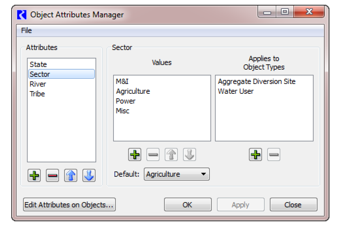
The dialog has three main areas as described right to left.
• Attributes. Add or delete an attribute using + and - buttons. Rename by double-clicking the name. Move the selected items up or down within the list with the arrow buttons.
• Values. Define the legal values for each attribute. For the selected attribute, the center list shows the legal values. Add or delete a value using + and - buttons. Rename by double-clicking the name. Move the selected items up or down within the list with the arrow buttons. The Default menu is used to specify the default value for new objects or the first time you apply the attribute to a set of objects. There is no automatic or predefined NULL or NONE value. You must create this if desired. The empty string is not allowed as a value.
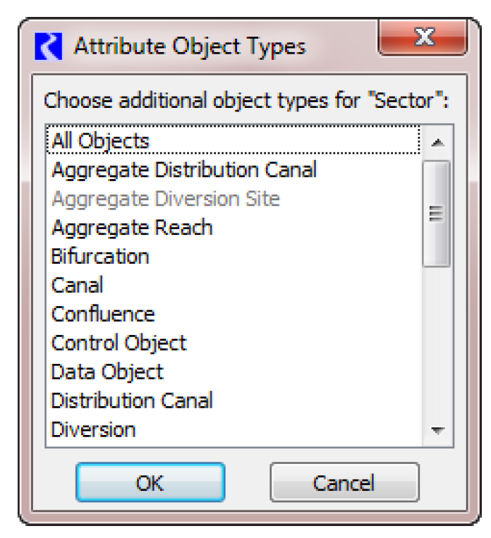
• Applies to Object Types. For the selected Attribute, add or remove the object types to which this attribute applies using the + and - buttons. Object Types are always listed in alphabetical order. The first one is All Objects.
Additionally, if any of the selected set of values (to be removed) are currently used on any objects, a warning message will be displayed indicating which values are used and the number of objects using them.
Right-click context menus allow you to add and delete functions, as well as copy and paste (for text to and from the system clipboard).
Import and Export Attributes and Values
Sometimes, you may wish to move attributes and values from one model to another. Use the Import and Export features on the Object Attributes Manager.
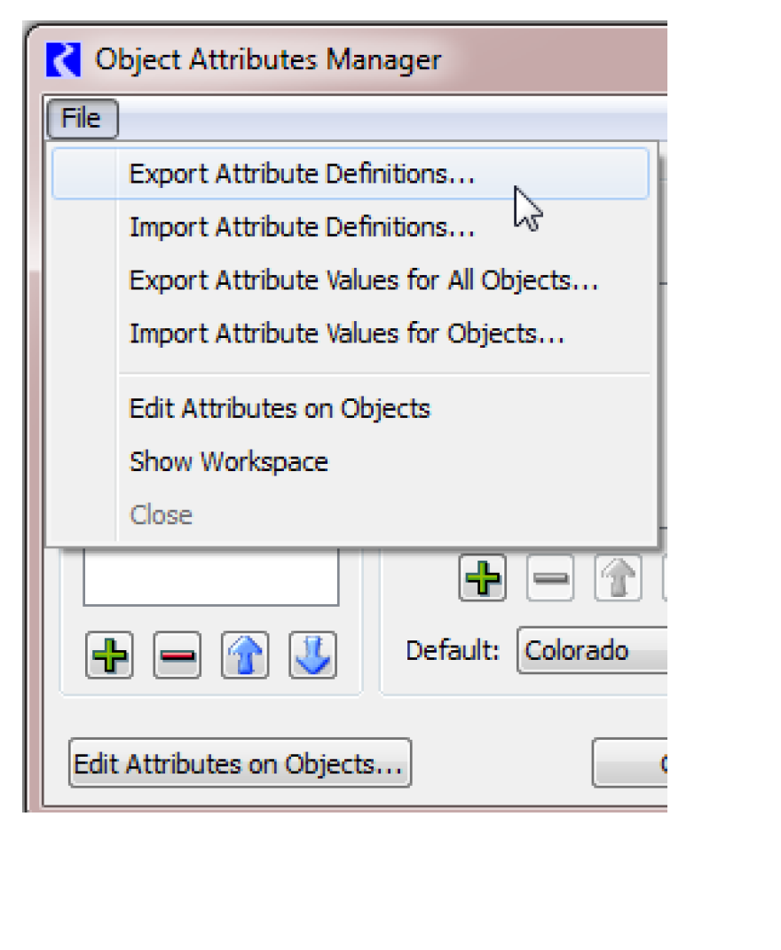
The following is a description of the actions in the File menu for importing and exporting.
• Export Attribute Definitions. Export only the attribute definitions including the Attributes, legal values, and the possible objects types on which they can be used.
• Import Attribute Definitions. Import the attribute definitions that were exported.
• Export Attribute Values for All Objects/ Export the Attribute values specified on each object. For example, this would export that LakeA has the value Colorado for the State attribute.
• Import Attribute Values for Objects. Import the attribute values that were exported.
To copy all attributes and values from one model to another model that has no attributes defined, you would need to export both the definitions and values. Then in the new model, import the definitions first and then the values.
Edit Attributes on Objects
The Edit Attributes on Objects dialog displays the attributes and value for a selection of objects, and supports applying new values to all or some of those objects. Figure 4.18 illustrates the tool.
Figure 4.18
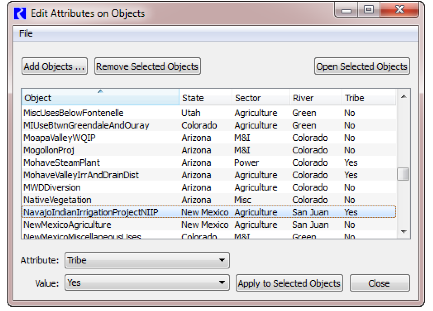
The following features are supported:
• Add objects to the list of objects by selecting the Add Objects button. Use the selector filter Has Attribute Value to find objects that already have the desired Attribute/Values. See “Selecting Objects” for details.
• Each object is added as a row in the table.
• Remove the selected objects in the list by selecting the Remove Selected Objects button.
• Use the Open Selected Objects button to open the selected set of objects to their Attributes tab.
• Each column represents an attribute defined in the model. The values are then shown on each row. If an attribute does not apply to a selected object, the cell is blank.
• Columns are sortable and rearrange-able.
• Use the right-click context menu to copy a list of objects, attributes, values to the system clipboard.
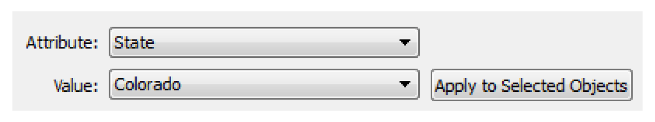
To change the value of a particular attribute for one or more objects shown in the dialog,
1. Highlight/select the desired objects.
2. Select an Attribute and the new Value from the menus at the bottom of the dialog. In this example screenshot, we have chosen the State attribute and want to assign the specified objects to have the Colorado Value.
3. Select Apply to Selected Objects to apply that value to those selected objects.
The change is immediate.
Accessing Attributes from RPL
To access Attribute and Value information from RPL, use the following predefined functions:
• ObjectAttributeValue - Get the value (as a string) for the specified Attribute on the specified Object. See “ObjectAttributeValue” in RiverWare Policy Language (RPL).
• ObjectHasAttributeValue - Return a Boolean of whether the particular Object has the specified Attribute Value. See “ObjectHasAttributeValue” in RiverWare Policy Language (RPL).
• ObjectsFromAttributeValue - Get a list of all of the objects that have the specified value for the specified attribute. See “ObjectsFromAttributeValue” in RiverWare Policy Language (RPL).
Multiple Object Method Selector
Before the Multiple Object Method Selector dialog box was available, a user had to select methods from the Open Object dialog for each object. For example, if a new engineering method was developed for use for all reservoirs in basin, a user would have to select this new method on each Reservoir object. For large models, this could be a tedious and time-consuming task. The purpose of the Multiple Object Method Selector is to allow the user to set an engineering method for a group of objects from a single dialog.
All objects of the same type do not necessarily have the same engineering methods or method categories available. For example, it is not always possible for a user to select a given method on all Level Power Reservoirs. The currently selected engineering methods on an object determine the currently available methods and method categories.
To overcome these difficulties, this dialog indicates which objects have a given method category available and therefore which objects will need to be re-configured in order to make the given category available. The dialog similarly indicates which engineering methods are available on each object for a given category. Once an engineering category and method is selected, the dialog only changes the engineering method on objects which have the desired category and method available.
Usage Overview
• Open the Multiple Object Method Selector from the main RiverWare workspace by selecting Workspace, then Objects, then Select Methods on Objects.
• Add objects to the object list by selecting the Add Objects button, then select objects in the object selector and select Ok.
• Optionally, filter the objects by type.
• Highlight the desired objects to which a new method should apply.
• Select a category from the category list.
• Verify that the category is available on the desired objects by inspecting the Current Method column in the object list.
• Select a new method from the method list.
• Verify that the selected method is available on all desired objects by inspecting the Available column in the object list.
• Apply the new method to the highlighted objects by selecting the Apply New Method button.
• Verify that the objects listed in the confirmation dialog are the objects you intend to affect, and select OK.
Accessing the Dialog
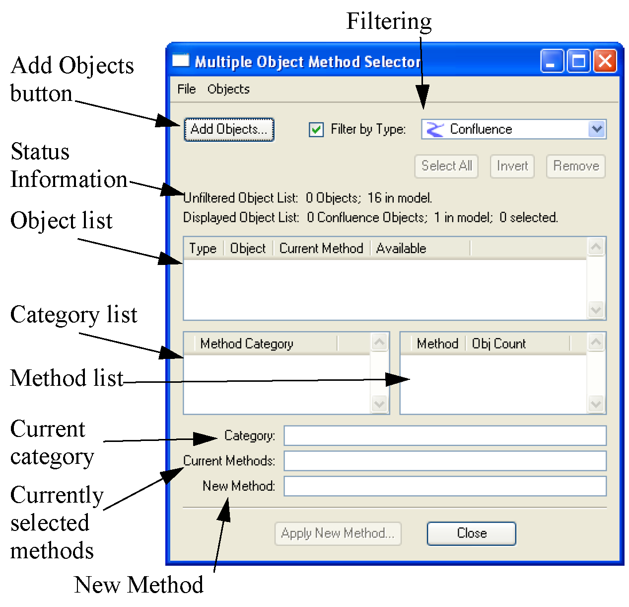
The dialog is invoked from the main RiverWare workspace using the menu sequence: Workspace, then Objects, then Select Methods on Objects. This displays a blank Multiple Object Method Selector dialog.
Figure 4.19
It is also possible to bring up the dialog from the Open Object, Methods tab by right-clicking a row and then selecting Show in the Multiple Object Method Selector. In this case, the selected object is added to the object list and the selected category and method are already highlighted.
Dialog Overview
Selecting methods on multiple objects consists of the following steps:
1. Select a group of objects.
2. Select a method category.
3. Select a new engineering method.
These steps are accomplished using the three sections of the dialog. The dialog is designed so that the user progresses from top to bottom with each successive task. From top to bottom, we will refer to these sections as: Object List, Category List, and Method list.
Object List
The selection of new methods is performed on the selected objects in the list of objects. This list is created/edited by the user by adding/removing objects, filtering, and finally making a selection.
Adding Objects
Adding objects is accomplished using the selector. This dialog is displayed using the Add Objects button or the corresponding menu item: Objects, then Invoke Object Selector.
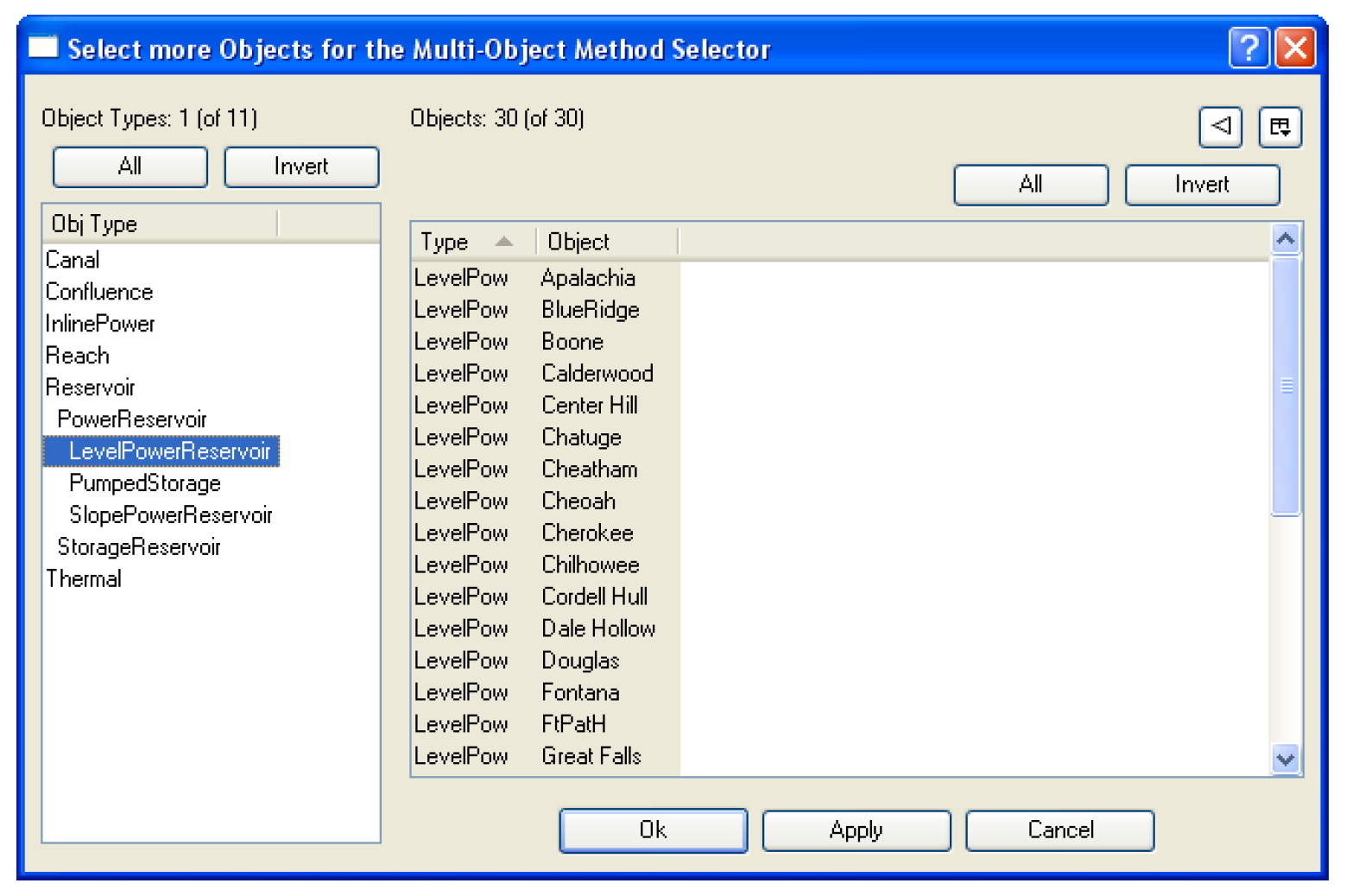
Use of this dialog proceeds from left to right. The user first selects an Object Type. This populates the list of objects of the given type in the Objects list. Multiple object types can be selected simultaneously by pressing Ctrl while selecting the object types.
Objects in this list can be filtered using the standard object filters: Object Name Filter, Has Accounts Filter, and In Subbasin Filter. The user then selects objects from this list. This can be done with the following methods:
• Manually selecting individual objects;
• Selecting multiple objects by Ctrl on the keyboard and selecting multiple objects with the mouse;
• Selecting all the objects in the list by selecting the All button under the Object list in the dialog.
Once the desired set of objects has been selected, the OK or Apply button adds the objects to the list in the Multiple Object Method Selector. See “Selecting Objects” for details on using the selector.
If after adding objects to the Multiple Object Method Selector, more objects need to be added, the object selector can be invoked again. Objects are appended to the current object set in the Multiple Object Method Selector.
Note: The list of objects added using the selector is called the unfiltered list and can contain many different types of objects.
Note: Regarding aggregate objects, parent aggregate objects and their child segment objects appear as separate items in this object selector dialog. The parent object will appear as an object of the aggregate type. The child objects will appear as objects of their individual type. For example, an AggReach with 2 child/segment objects are treated as follows: the parent object is an object of type AggReach; the 2 child objects are objects of type Reach. They can each be added by selecting the given type then the given object.
Removing Objects
A user removes objects by selecting one or more objects in the list and then clicks the Remove button or all objects can be removed using the menu item: Objects, then Remove All Objects.
Filtering Objects
When the user adds objects to the list using the Add Objects button and the selector, the user is able to select multiple types of objects. Applying new methods is specific to a type of object, e.g. Reach methods do not apply to Reservoirs. If the user adds multiple types of objects, every method category for all object types will be added to the list. It is frequently overwhelming to sort through the various user methods to find the desired method. To avoid this, the object filter can be used to only show objects by type. Select the checkbox to Filter by Type, then select a type of object from the menu. Abstract object types like Reservoir or Power Reservoir can be selected. Now only the objects matching that type are shown in the list. This is now called the filtered list.
Note: If you wish to switch object types, the original list of objects added remains as the non-filtered list. Select a new filter type (including disabling the toggle) to show a different set of objects. The status of the number of objects in the filtered and unfiltered objects lists is shown on the dialog. This filtering functionality allows users to add all the objects in a subbasin or geographic region, then select methods on each type of object without losing the list of objects in the subbasin.
Selecting Objects
Application of a new method is performed on the objects selected in the object list, not all of the objects displayed. You can use the following methods to select objects:
• Manually select individual objects.
• Select multiple objects by highlighting multiple objects or use the <Control> key on the keyboard.
• Select all the objects in the list by selecting All under the Object list in the dialog.
• Invert the selection using the Invert button.
Any new method selection will be applied only to the selected objects.
Selecting a Method Category
Once objects have been added to the object list, the category list will be updated to display the union of all active categories on the selected objects. It is important to understand that this list displays the union, so some objects may not have a given category available.
Note: Object Level Accounting Methods are shown with a grey background.
Selecting a category selects the category. When a category is selected the object list and method selection controls are updated to display information about the selected category.
Determining Which Objects Have a Category Activated
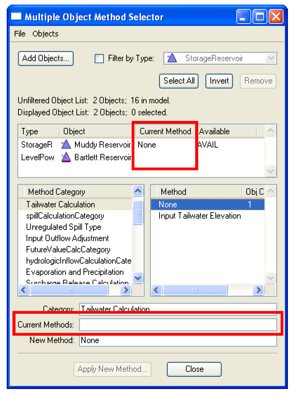
When a category is selected, the object list displays which objects have the selected category available. The third column in the object list, Current Method, is one of the following:
• Empty - indicating that the selected category is not available on this object
• Displays a method name - indicating that the selected category is available, and that the displayed method is the currently active method for the category on this object.
The user should scroll through the object list, looking for empty values in the third column. This information is useful when the user intends to set a common method on all the objects in the set. In this case, the user can quickly determine which objects need to be reconfigured to make the desired category available.
Determining the Currently Active Method
Information about the currently active method is contained in two places in the dialog: the Current Method column in the object list, as discussed previously, and the Current Methods text box in the method selection section. The Current Methods line displays a comma-separated set of selected method for all the objects in the set.
Selecting a New Method
Once a category has been selected, the user can select a new method for this category. The new method is selected from the list of methods in the right pane. Once a method is selected, it is added to the New Method line at the bottom of the dialog.
Like method categories, methods may not be active on some objects, even though their category is active. The method list displays the union of all methods available on the selected objects that have this category active. Since some methods may not be available on all objects, the object list displays whether a given method is available on each object. Once the user has selected a new method from the method list, the objects list is updated. The forth column in the object list, Available, now displays the text AVAIL if the selected method is available on the given object, or display nothing if the method is not available on the object.
Once a method has been selected the user should scroll through the object list to determine which objects can have the new method activated. Any method with AVAIL in the Available column are allowed to have the new method activated. If this column is empty for an object, the object will not be affected if this new method is applied.
Unlike the OpenObject dialog, selecting a method from this menu does not immediately set the method on all affected objects. Instead, the user must select the Apply New Method button to change the method on the objects. This Apply New Method button remains inactive until a new method has been selected from the menu, at which time it will be enabled. Selecting Apply New Method will set this method as the active method on highlighted objects in the object list with this category and method available.
Confirming Changes
After the new method has been applied using the Apply New Method button, a confirmation dialog appears. This dialog lists all the objects which will have this new method activated. This is the selected objects the list that have the desired category and method available. Canceling this dialog will prevent the method from being changed on any of the objects. Also, the dialog informs the user of the new slots which may be instantiated when this new engineering method is activated. Canceling this dialog will prevent the method from being changed on any of the objects.
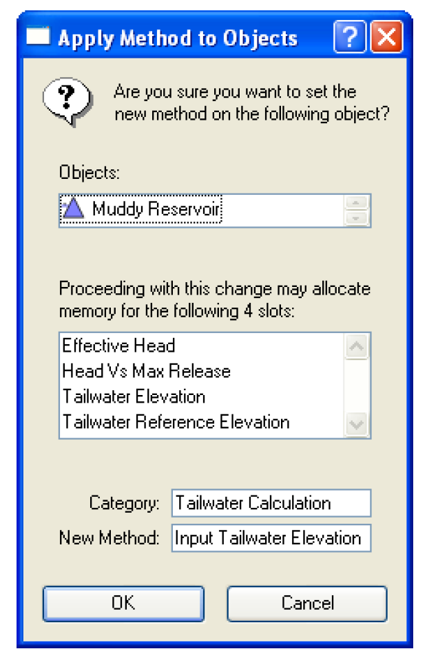
Once the confirmation dialogs have been accepted, the objects will be modified. A busy cursor indicates that the methods are being changed. For a large set of objects this operation can take some time.
Once the methods have been changed, the Multiple Object Method Selector dialog will be updated to display the new methods on the objects. A quick inspection of the object list shows that the method has been changed on the objects with this category and method available.
Selecting Object Level Accounting Methods (OLAMs)
The Multi-Object Method Selector dialog can be also used to select Object Level Accounting Methods (OLAMs). See “Object-level Accounting Methods (OLAMs)” in Accounting for details on OLAMs. Figure 4.20 shows aspects of this dialog specific to OLAMs.
• OLAM category items are shown with a grey background. In Figure 4.20, see the bottom three rows in the method category list.
• When an OLAM category is selected, additional controls are shown below the method list. In Figure 4.20, see the Method Execution Time selector and Set button. These controls are described on the following pages.
Figure 4.20
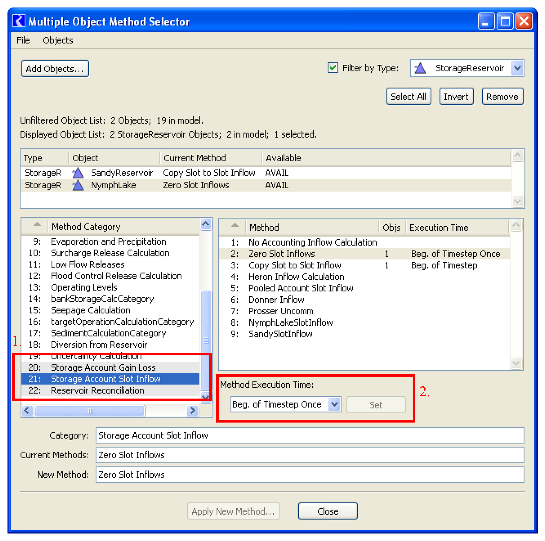
Setting the Execution Time of OLAMs
When an object level accounting category is selected, that category’s method options are shown in the methods list (shown here).
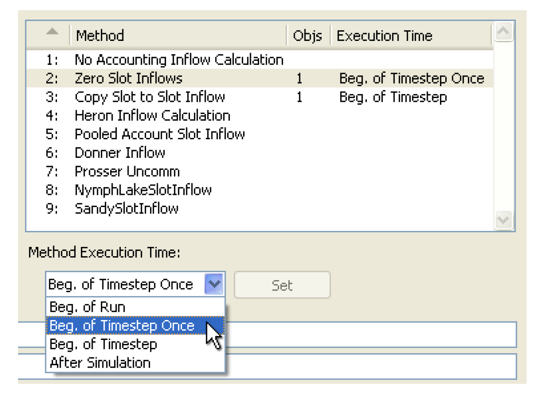
When selecting a method item selected on at least one simulation object, the Method Execution Time combo box is set to the indicated execution time -- or, if multiple execution times are indicated for that method item, one of those several execution times are used. You can selected a different execution time in the combo box. See “Execution of OLAMs” in Accounting for details on execution times.
In this dialog, there are two ways of setting the execution time of OLAM methods:
• By selecting the Set button next to the Method Execution Time selector. This effects the methods on the objects currently having that method setting.
• By selecting the Apply New Method button at the bottom of this dialog. (See previous page). This simultaneously sets the selected method item on the selected objects AND sets the execution times of those methods.
Special Support for Copy Slot to Slot Inflow: Set Target Account List Slot
The Multiple Object Method Selector also has special features for the Copy Slot to Slot Info OLAM; see “Copy Slot to Slot Inflows” in Accounting for details.
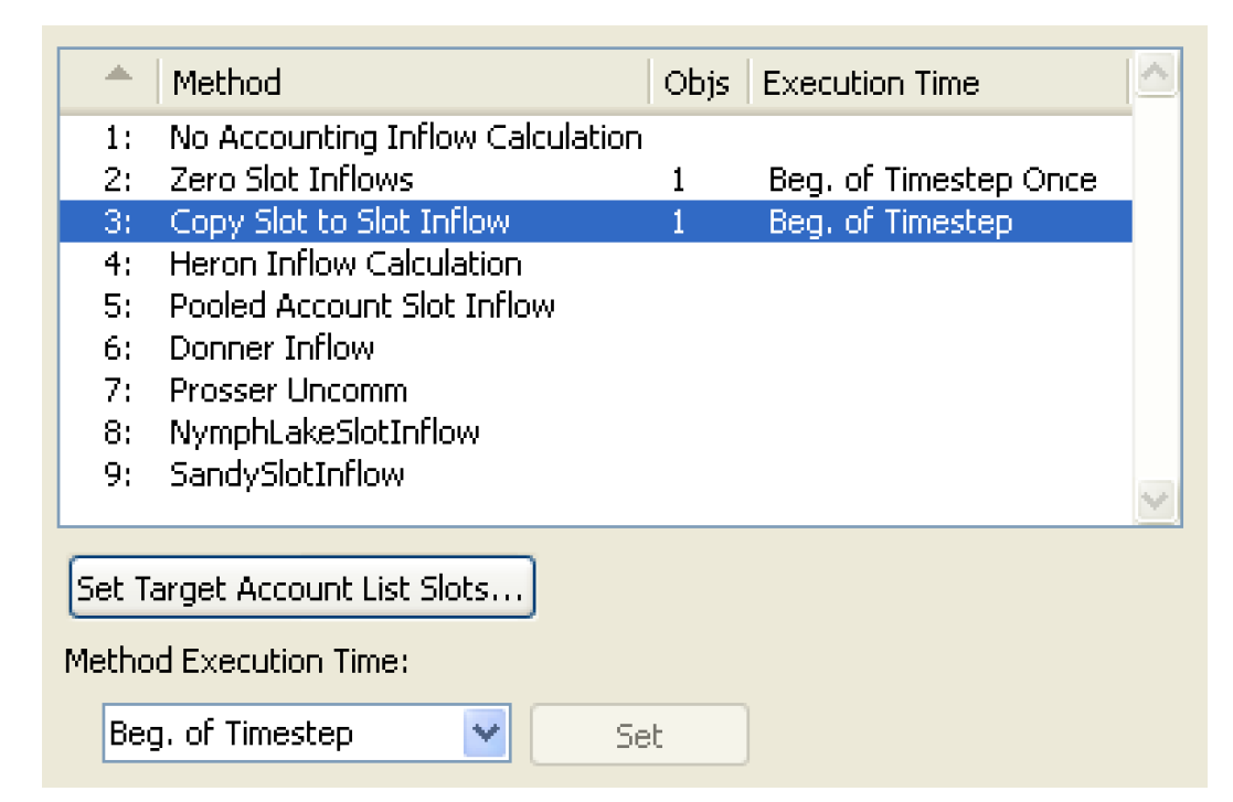
When that method is selected, the Set Target Account List Slots button is shown below the methods list. This button is enabled if any objects currently have the Copy Slot to Slot Info method selected. Selecting this button brings up the new Set Target Account on Objects dialog.
The Set Target Account on Objects dialog operates on each simulation object being editing in the Multi-Object Method Selector which has the Copy Slot to Slot Inflow method selected.
Figure 4.21
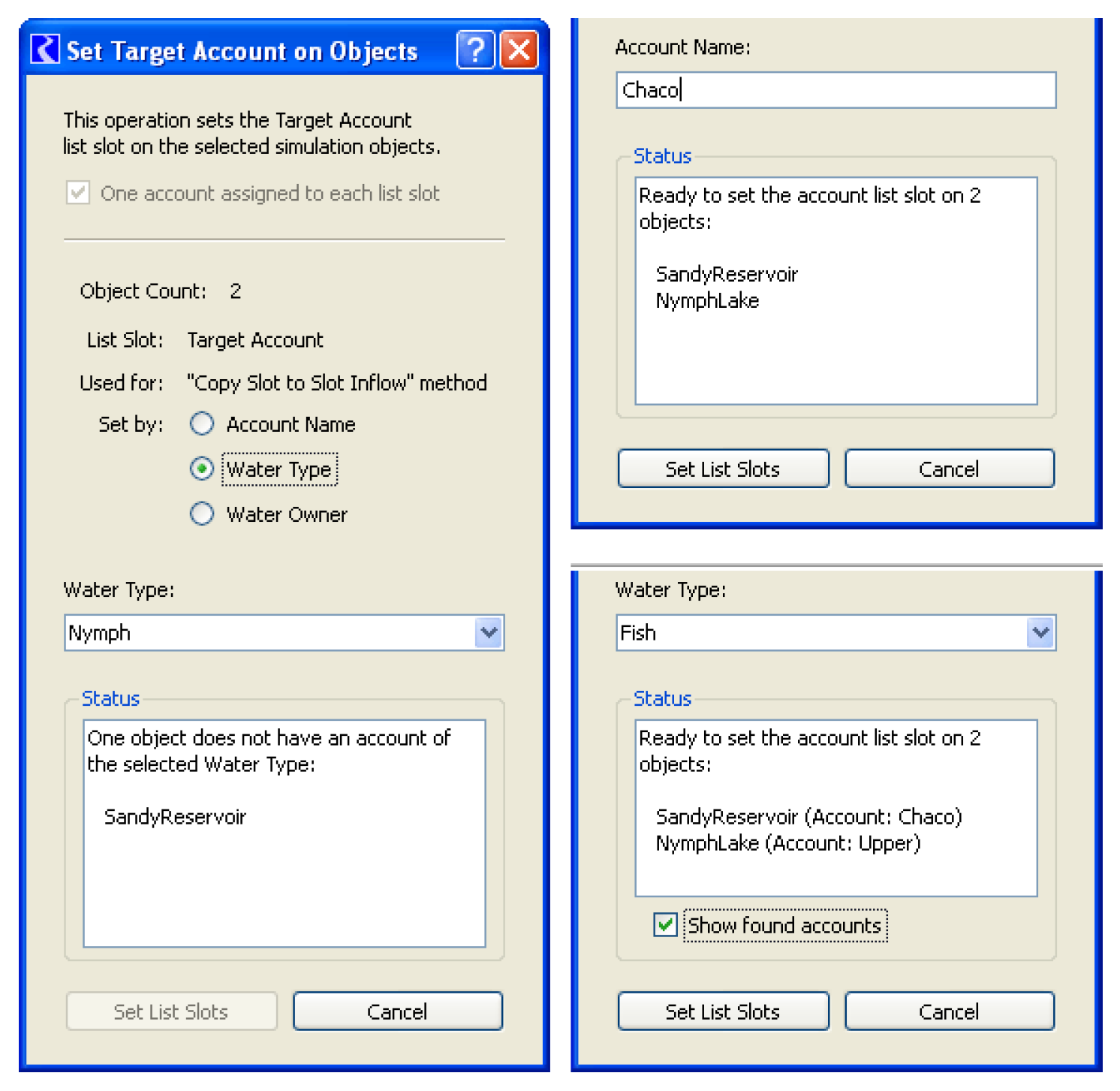
The user selects one of three criteria for choosing an Account on each simulation object to be assigned to that object’s Target Account List Slot:
• Account Name
• Water Type
• Water Owner
There must be exactly one Account on each object matching the criteria. This information is displayed in the Status area.
In the case of the Set List Slots operation being ready (i.e. exactly one Account matching the entered criteria for each simulation object), the Status panel enumerates the simulation objects; see Figure 4.21. Otherwise, the Status panel enumerates the simulation objects which either have no Accounts matching the criteria, or have more than one Account matching the criteria. Additionally, when the Water Type or Water Owner criteria are selected, the names of the matching Accounts can optionally be shown.
Selecting the Set List Slots button, when enabled, assigns the object Target Account List Slots and closes the dialog.
Revised: 11/11/2019