
Data Management Interface (DMI)
Database DMI
The Database DMI provides a direct connection between RiverWare and an external database. Databases currently supported are the U.S. Army Corp of Engineers Hydrologic Engineering Center’s Data Storage System (DSS), the Hydrologic Database (HDB), and Microsoft Excel. Following are the slot types that can be read or written by each type of DMI:
• The DSS interface supports series data and paired data (Table Slots with two columns).
• The HDB interface supports series slot data.
• The Excel interface support series, periodic, table, and scalar data.
This section presents an overview of the Database DMI, then presents details on creating database DMIs, datasets, name maps, and sharing database DMIs.
Overview
The Database DMI allows RiverWare to import and export data directly from and to the database. In this document, a database refers to a specific database implementation, for example a DSS file or Excel workbook. Figure 4.1 shows the interaction between RiverWare, the DMI Server and the database. The user sets up the Name Maps, configures the Datasets, and identifies slots and time intervals at which to import/export data in the Database DMI.
Figure 4.1
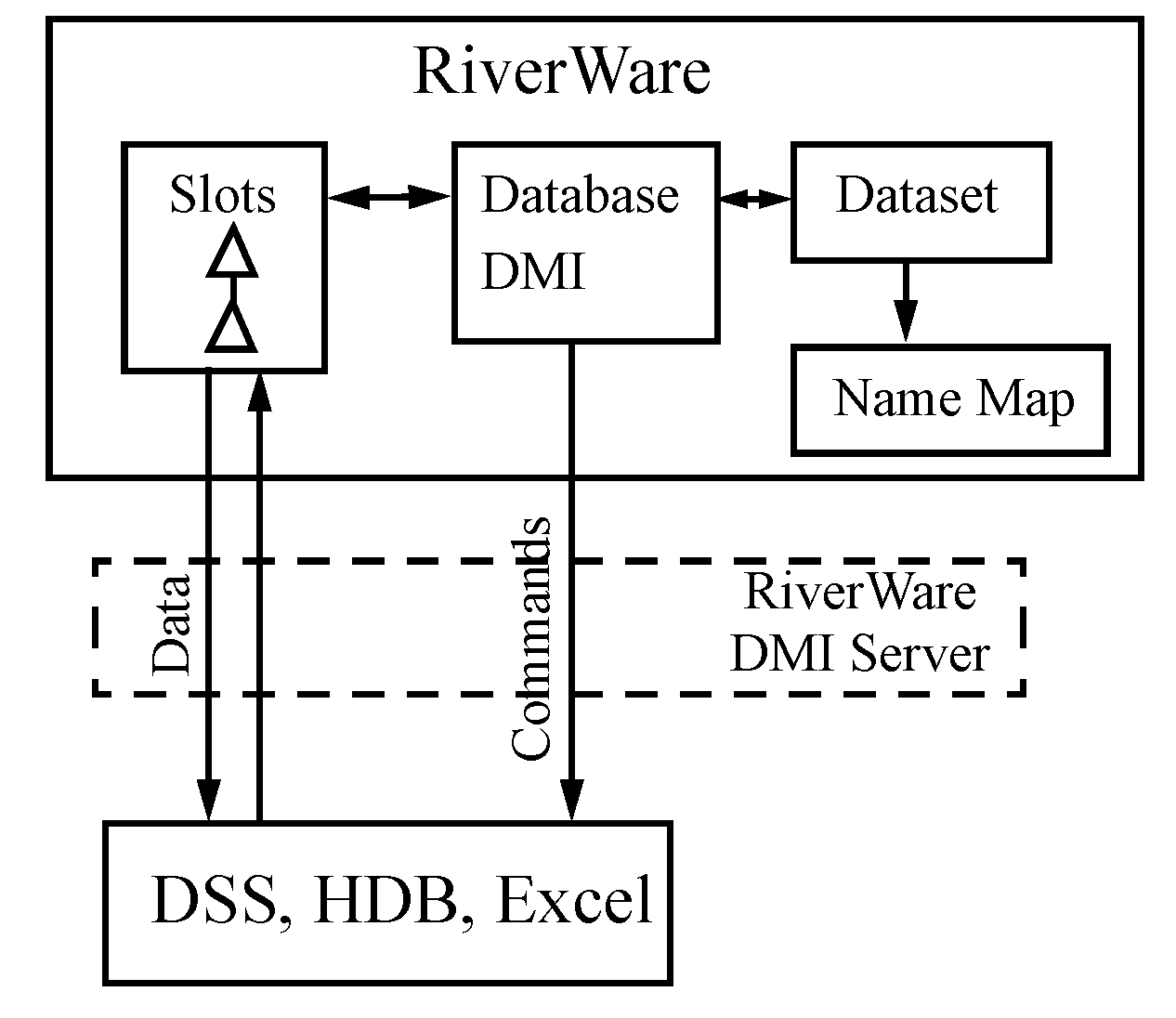
When the Database DMI is invoked, the Dataset and Name Maps are read specifying the database to use, the units and what slots/objects are named in the database. Any wildcarded slot selections are then fully specified and then any Name Maps are applied. Then commands are passed to the DMI server: for an input DMI, the server locates the data in the database and imports data into RiverWare slots; for an output DMI, the server takes the RiverWare slot data and inserts it into the appropriate place in the database.
Note: The DMI server is a separate application included with the RiverWare installation package. It is not visible to the user and no further discussion is presented.
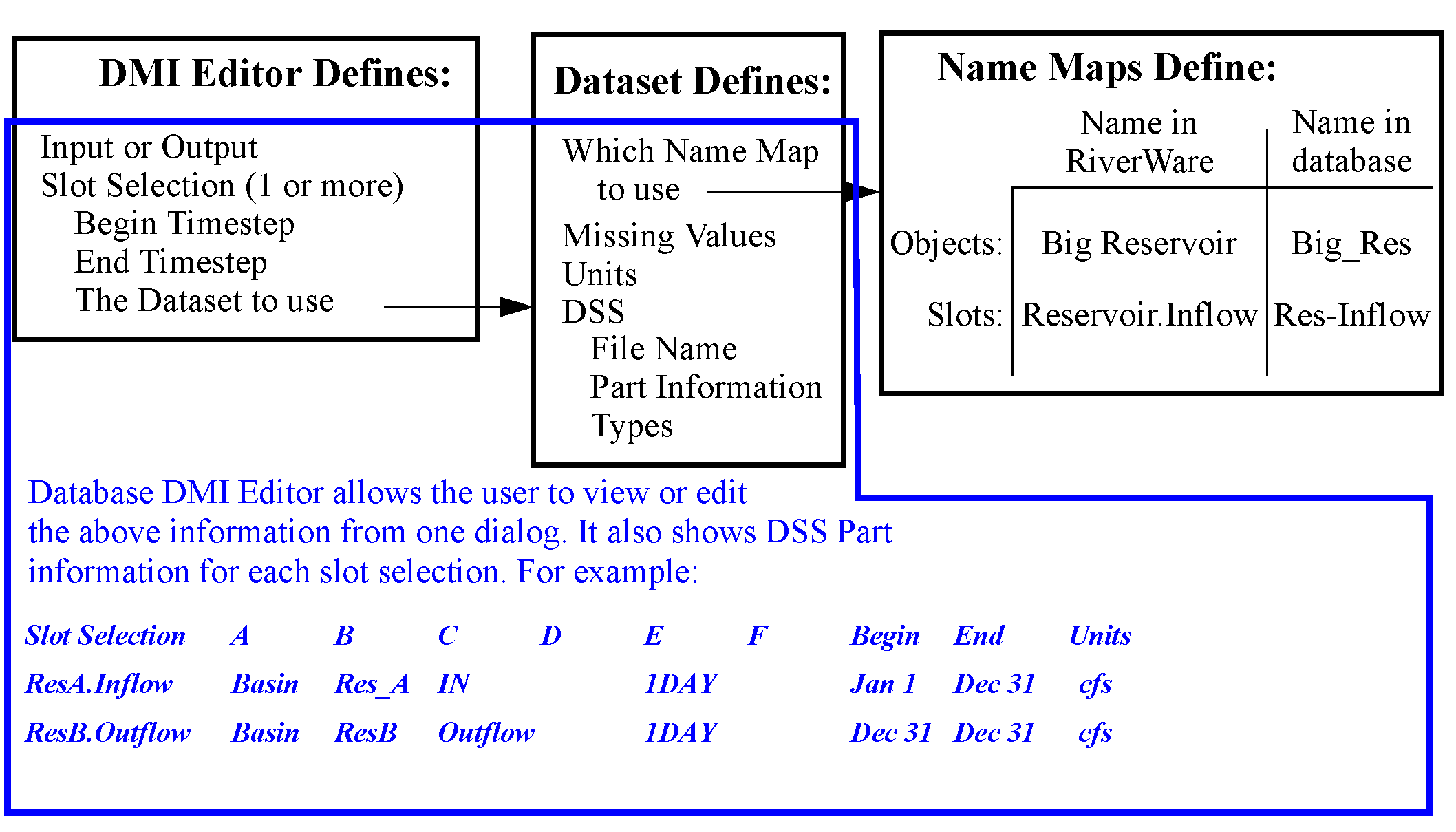
Figure 4.2 shows in more detail the three pieces of a database DMI and how they work together to define a DMI.
Note: With the DMI Database Editor you can configure an entire Database DMI in one dialog but these three components still exist and interact with one another. See “Creating a Database DMI” for details.
Figure 4.2
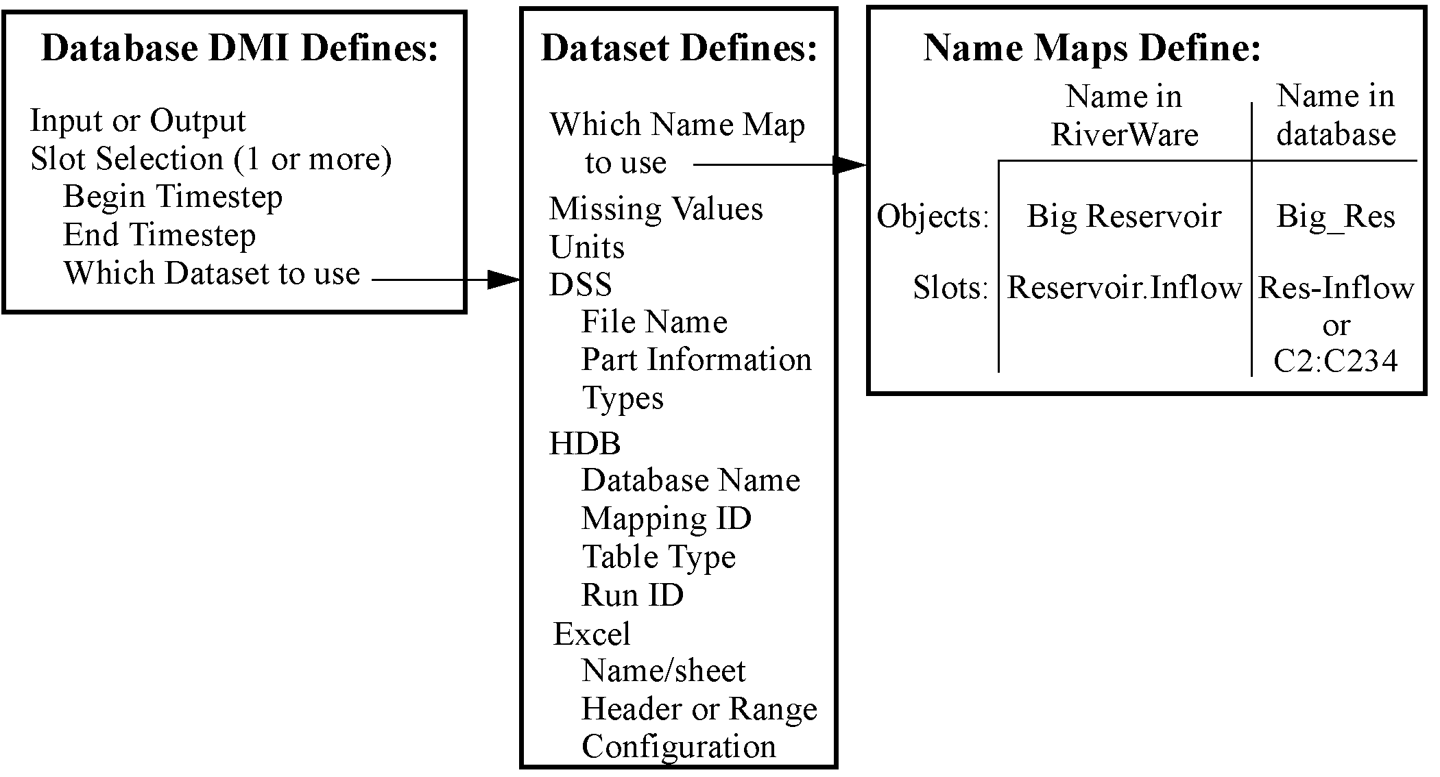
The three pieces (slot selections, datasets, and name maps) were designed to be very flexible. In the simple case of importing or exporting 1 slot, the user needs 1 slot selection, 1 dataset, and optionally 1 name map (DSS only). It is possible to configure the system with more functionality which leads to more complexity.
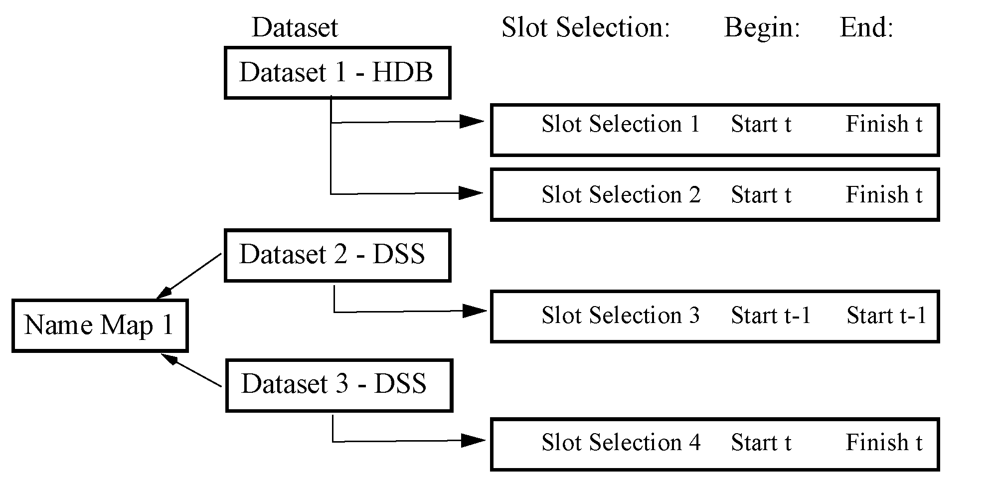
For example, in Figure 4.3, slot selections 1 and 2 share dataset 1 which is an HDB dataset; no Name Map is required. In this DMI, Slot selection1 is an input from HDB for the full run and then slot selection 2 is an input from HDB for the full run. Slot selection 3 is used to input initial conditions and uses Dataset 2 which points to a separate DSS file in Dataset 2. Slot selection 4 inputs from a DSS file referenced in Dataset 3 for the full run. Both Dataset 2 and 3 are DSS datasets and share Name Map 1.
Figure 4.3
We will now look at each component starting with creating a Database DMI, then look at Datasets followed by Name Maps.
Creating a Database DMI
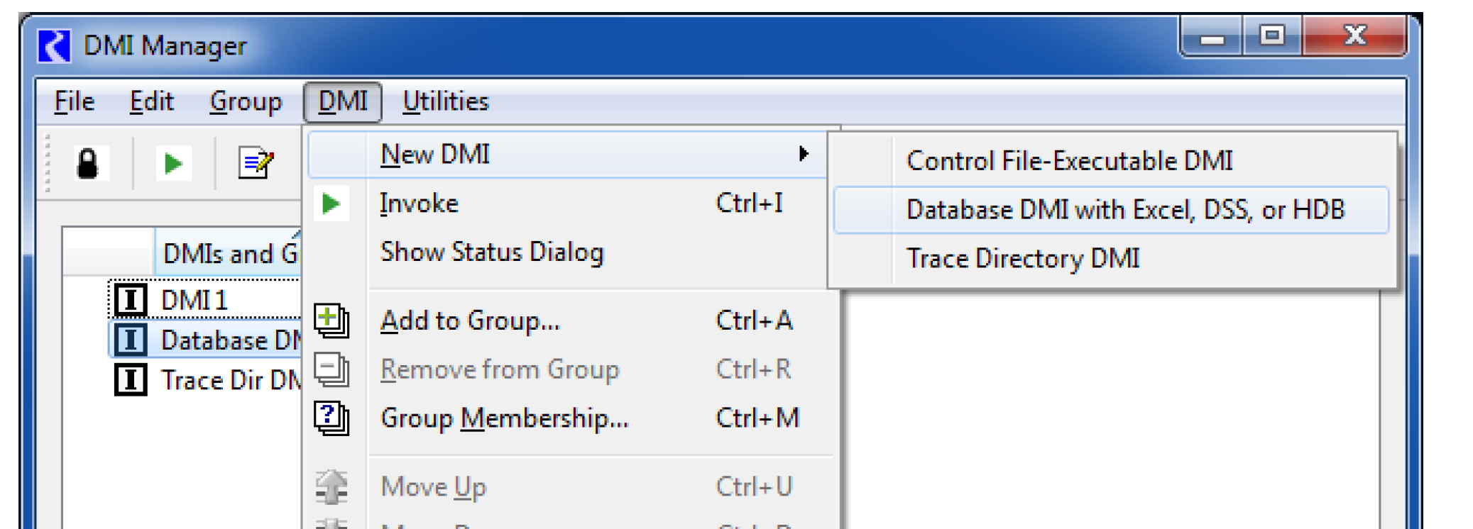
A Database DMI is created from the main DMI Manager dialog using the DMI, then New DMI, then Database DMI with Excel, DSS, or HDB menu.
There are two ways to define and edit a Database DMI:
• Define a Name Map, Dataset and then use the Database DMI editor: You create a Name Map, then a Dataset, then a Database DMI that pulls it all together.
• Use the Database DMI Editor: The Database DMI Editor allows you to create a fully functional DSS Database DMI from a single dialog and provides access to other dialogs for Excel and HDB DMIs. It fully expands the slot selection to show the exact configuration that will be used. For example, it displays that BigReservoir.Inflow will be imported using BigRes Res-Inflow and displays the part information and units that will be used.
Once a new Database DMI is added to the DMI manager, the user can edit it using the Database DMI Editor. The Database DMI Editor dialog provides a convenient place to create, edit, and view database DMIs. It also provides a single dialog for configuration of a fully functional DSS Database DMIs. To that end, it allows the user to specify all required configuration information and as much optional configuration information as is feasible. The real power of this dialog is that the user can see the fully specified information that will be sent to the database, which is especially useful for DSS.
To open the New Database DMI Editor, the user selects Edit, then Edit with New Database DMI Editor. The Database DMI dialog appears.
This dialog is like an editable view into the Dataset Manager. Thus, the user can see what has already been configured in those dialogs but also make edits that will be applied to those pieces. It is important to note that if the user edits a dataset or Database DMI in the editor window, the user cannot also edit the individual components at the same time.
Note: Because there are many approaches to create and edit Database DMIs, there are multiple ways to edit the same information, e.g. you could edit a dataset from both the dataset manager and the Database DMI Editor. To avoid conflicts, the dialog that first starts editing a name map or dataset creates a “lock” on the information and no other dialog can edit that feature. When a lock has been created, the lock icon  is added to any other dialogs that are trying to edit that information. If you see this icon, the information is not editable from that location. Similarly, if a name map or dataset has been scheduled for removal from another dialog, the “delete lock” icon is shown.
  .
.
is added to any other dialogs that are trying to edit that information. If you see this icon, the information is not editable from that location. Similarly, if a name map or dataset has been scheduled for removal from another dialog, the “delete lock” icon is shown. .Figure 4.4 shows a similar figure to the one presented in “Overview”, but with the Database DMI Editor also shown.
Note: The information in each of the components is represented in the dialog, but in a slightly different organization. The parts of the dialog are described in detail in the following section.
Figure 4.4
Conceptually the dialog has four sections from the top to the bottom, as shown in Figure 4.5 and described in the following sections:
• Database DMI Name and Type
• DMI Configuration
• DSS Configuration including DMI User Parameters (Only shown when a DSS dataset is present)
In this dialog, each type of dataset has its own color:
• HDB - Orange
• Excel - Green
• DSS - Pink
Figure 4.5
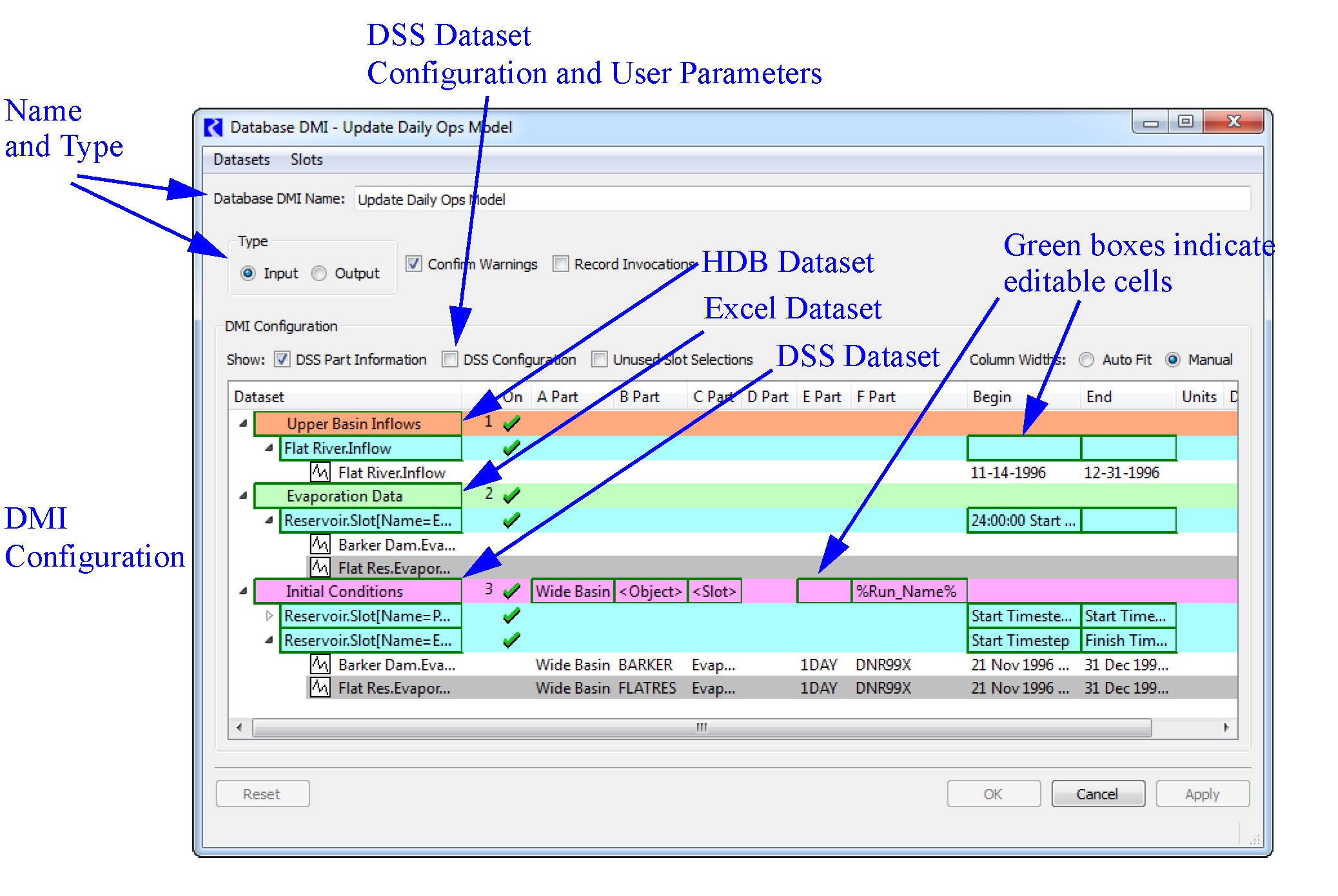
The cyan rows are slot selections. The green boxes are cells in which data entry is possible.
Name and Type
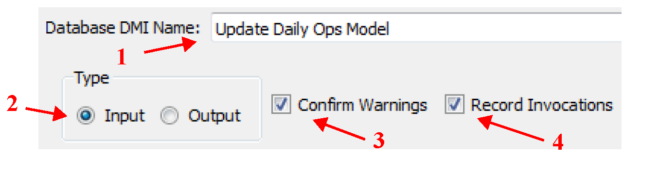
The Database DMI general configuration section (upper section) of the dialog allows you to do the following:
• Specify the Database DMI Name in the text field.
• Specify whether the Database DMI is an Input or Output DMI.
• Specify if you wish to confirm warnings before the Database DMI continues using the toggle.
• Specify whether he DMI manager should record invocations of the DMI. The Record Invocations check box allows RiverWare to maintain information which chronicles input DMI invocations. With this information, values set by DMIs can be cleared on a per-invocation basis. If a user wishes to clear out all values that are input by a DMI, this box should be checked. If a user knows values set by a particular DMI won’t be cleared then it is not necessary to maintain information about the DMI invocations and this box should remain unchecked. (The information occupies memory and could, over time, degrade performance.) The checkbox is only enabled for input DMIs and the default is unchecked. See “DMI Invocation Manager Dialog” for details on clearing values set by an input DMI.
DMI Configuration
The DMI configuration section (middle section) displays the configuration of the DMI. In this dialog, each type of dataset has its own color:
• HDB - Orange 
• Excel - Green 
• DSS - Pink 
The light blue (cyan) rows  are slot selections. The
  are cells in which data entry is possible. This portion of the dialog allows you to:
are slot selections. The are cells in which data entry is possible. This portion of the dialog allows you to:• Create Datasets using the Dataset menu.
• Remove Datasets using right-click context menus.
• Create and define slots selections and time intervals.
• For DMIs with DSS datasets, see and edit the part information for each slot.
• Hide the part information using the DSS Part Information toggle.
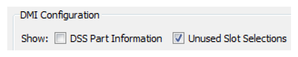
• Show or hide Unused Slot Selections; see “Unused Slot Selections”.
• Select either Auto Fit or Manual Column Widths.
Note: The first column in Auto Fit mode, only grows to a fixed maximum width.
• In this dialog, tool tips and the status bar (the lower left) are used to show the contents of cells, indicate directions, or additional information.
The information is presented in a tree-view, with each level representing a more detailed specification, as detailed in Table 4.1.
Name | What it is | Tree Level | Items shown |
|---|---|---|---|
Dataset | Entered by user | 1: Highest | Name, type and generic Part information. The Name and Part information is editable. All Datasets including HDB and Excel Datasets, are listed. HDB and Excel datasets can be shown in this dialog but cannot be edited. |
Slot Selection | Slot Selection Name as shown (or modified) in the Selector dialog. It can included wildcards, e.g. StorageReservoir.Outflow | 2: Middle | The begin and end timestep for this selection are shown and can be edited. |
Slots in Selection | Slots that were selected by the Slot Selection shown, including resolution of wildcards | 3: Lowest | Fully specified information as it will be passed to the database. For DSS, this includes Part information, Begin and End Timestep, and units. No editing is allowed |
The following sections describe the editable parts of each of the levels of the treeview.
Dataset
The following actions can be done for a Slot Selection row:
• Name DSS Datasets. Double-click to edit the name.
• Open HDB and Excel datasets. Double-click HDB or Excel datasets to edit.
• Disable a Dataset for debugging; see “Enabling and Disabling for Debugging”.
• Specify the part information. There are many options for specifying the part information. The only restriction is that Part D is not editable and the default for Part E is the timestep size. The part information can be edited by entering text or by selecting text from a right-click context menu. In addition to typing text, you can use the two following items to generalize DSS DMIs:
– Workspace Entities.You can use generic Workspace Entities for wildcarding any part (except Part D which is not editable). Select the desired entity from the right-click context menu. Table 4.2 lists the options.
Workspace Entity | Description |
|---|---|
Slot | The slot name. |
Parent | The item that contains the slot. For a simulation slot, this is the object (e.g. a reservoir). For an accounting slot, this is the account (e.g. a storage account). |
SimObj | The object that contains the item. For both simulation and accounting slots, this is the containing object (e.g. a reservoir) |
Account | The name of the account containing the object. (Valid when accounting is enabled) |
Supply | The name of the supply. For example a supply named, ResAStorageToReachBFish.Supply would result in ResAStorageToReachBFish (Valid when accounting is enabled) |
Exchange | The name of the exchange. (Valid when accounting is enabled) |
Payback | The name of the payback. (Valid when accounting is enabled) |
UpSimObj | Not implemented yet. For a supply, this evaluates to the object that contains the upstream account. |
UpAccount | Not implemented yet. For a supply, this evaluates to the account name of the upstream account. |
DownSimObj | Not implemented yet. For a supply, this evaluates to the object that contains the downstream account. |
DownAccount | Not implemented yet. For a supply, this evaluates to the account name of the downstream account. |
Note: In versions prior to 6.1, Part B was by default the object name and Part C was by default the slot name. Now these need to be explicitly defined for new datasets, existing datasets will be given the <parent> and <slot> entities for parts b and c, respectively.
– User Parameters. You can use parameters in the DSS parts (see “DSS DMI User Parameters”, for details). To use the parameters in the DSS part information, specify the value with the percent sign:
%Parameter%
Slot Selection
The following actions can be done for a Slot Selection row:
• Select slots by selecting the name of the slot selection. Typically, this is NONE before the slots have been selected. Use the Selector to choose the desired slots. Either create a new selection or use an existing Slot Set (see “Slot Sets” in User Interface). When creating a selection, wildcards are very useful to symbolically specify the slots. For example, all Reservoir Inflows could be specified using a wildcard on reservoirs and on the slot name, Reservoir.Slot[Name=Inflow]. See “Creating a Name Map of All Reservoir.Inflow Slots” in User Interface for a step by step example of this selection.
Note: The Slot Selections are maintained as references to the specified slots. So if you delete the objects/slots to which the selection refers, the references could be lost, particularly if the slots are manually specified, that is, not using wildcards.The references are resolved when the Database DMI is opened. So if you want to export and re-import the same named data object (maybe from a different model) without breaking the DMI references, close all DMI dialogs, delete the object, re-import the new object and then open the DMI dialogs. The references will resolve and should point to the new object/slots. If you do this out of order, the references may be lost.
• Disable a Slot Selection for debugging; see d “Enabling and Disabling for Debugging”.
• Specify the time interval for each slot selection. The begin and end dates are edited in place; they can be edited by entering text or by selected text from a right-click context menu. In both cases the text is a symbolic date/time. If not entered, the default time range is the slot’s range. In the Begin and End columns, the user specifies the timesteps at which to begin/end the Input or Output data. The user can either select and manually type in the date, or right-click and a select from a list of commonly used reference datetimes as shown in the following figure. If selecting one of the reference datetimes, the user may enter the number of Timesteps in place of the letter N as necessary.
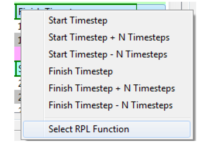
The datetime uses the same syntax as the RiverWare Policy Language (RPL) datetimes. For example, as shown in Figure 4.6, the user could enter either of the following as a valid datetime:
– 1:00 April max DayOfMonth, 2006
– 24:00:00 Start Month Start DayOfMonth, Start Year - 24 Hours
Figure 4.6
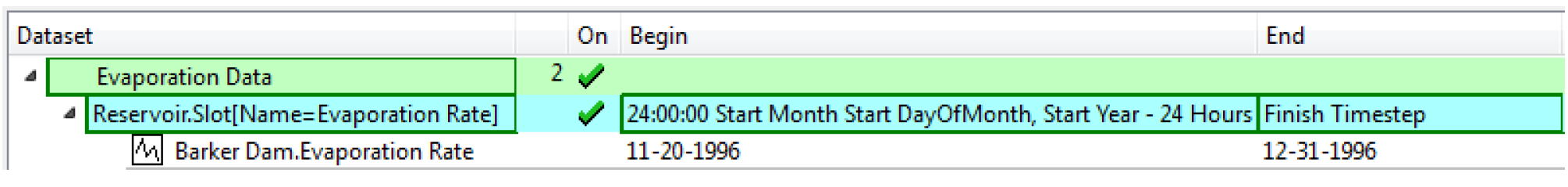
See “DATETIME” in RiverWare Policy Language (RPL) for details on datetimes. Basically, any fully specified datetime can be used
Note: No @ or quotes “ ” are necessary when specifying the datetimes in the DMI slots dialog.
To allow additional flexibility specifying datetimes, the user can choose the Select Function From Global Function Set option and then choose a RPL function from an opened Global Function Set; see “Global RPL Functions” in RiverWare Policy Language (RPL) for details. A RPL Object selector opens and displays a tree view of all the global utility groups and predefined function groups; see “Example: Creating a New RBS Ruleset” in RiverWare Policy Language (RPL) for details.
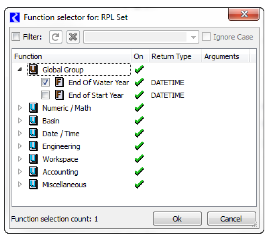
The user then selects a single function by selecting the box to add a check mark. This function MUST:
– Not have any arguments
– Return a fully specified DATETIME variable
If either is not true, an error will be posted when the selection is applied or the DMI is run. After selecting Ok, The function name is displayed in the Begin / End column with “( )” appended. Alternatively, a user may manually type in the function name, but must include the “( )”.
Slots in Selection
The following actions can be done for Slot Selection rows:
• See the slots that were selected using wildcard.
• See the resolved time interval for each slot, as it will be passed to DSS.
• See the units and scale as they will be passed to DSS.
• For DSS parts, mouse over the slot’s part columns to see the information that will be passed to DSS:
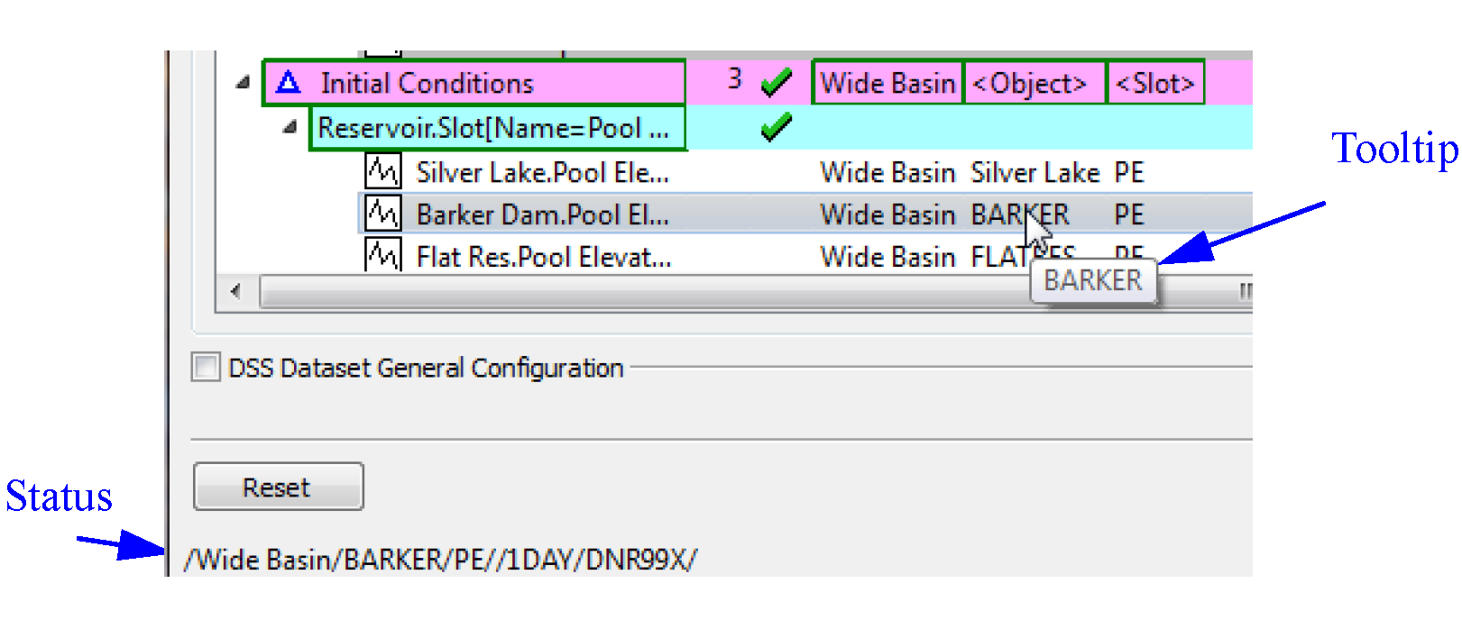
Figure 4.7 shows a fully defined DSS configuration.
Figure 4.7
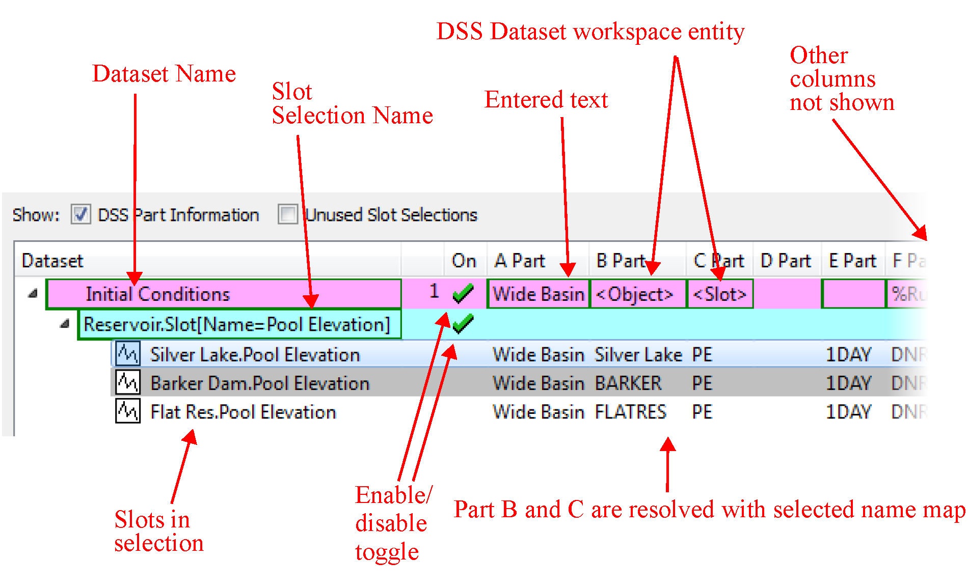
Figure 4.8 shows the right portion of the dialog.
Figure 4.8
Enabling and Disabling for Debugging
Datasets and slot selections can be disabled for debugging purposes. On the left part of each Dataset or Slot selection row, there is a green check if it is enabled. A red X indicates it is disabled. The purpose of this feature is to allow you to debug a DMI by disabling datasets or slot selections and then running the DMI to test other aspects of the DMI. This behaves as follows:
• Turning off a dataset causes its slot selections to be turned off.
• Turning off all slot selections causes the dataset to be shown as off.
• The dataset is shown as a tristate (on/green, off/red, partially on/orange) based on the state of its slot selections.
The on/off state is preserved in the model file when saved.
Use of Name Maps
If you specify a Name Map when configuring the Dataset, then the following will occur:
• If the RiverWare Object is in the Name Map then its mapped name will be used for <Object> or <Parent> entities; otherwise, its RiverWare name will be used.
• If the Slot is in the Name Map then its mapped name will be used for <Slot> entities otherwise, its RiverWare name will be used.
• If a Table Slot column is in the Name Map then its mapped name will be used for Part C; otherwise, the Table Slot’s RiverWare name will be used.
Unused Slot Selections
It is possible to have slot selections that are not used by any of the datasets. To show these selections, select Unused Slot Selections.
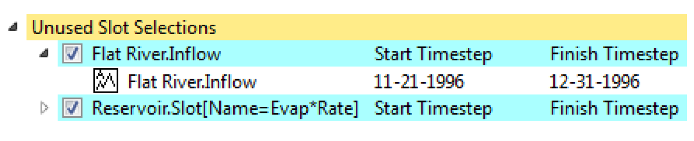
The selections are then shown as a golden colored row titled Unused Slot Selections at the Dataset level. You can view and change the selections (and the slots selected). From right-click context menus, you can delete the selection. You can also drag and drop the slot selection onto a dataset to associate that slot selection with a dataset.
DSS Dataset Configuration
For DSS datasets, an additional panel allows you to fully edit the dataset.
Note: This is not available for Excel or HDB. For those datasets, you can double-click the dataset and it will open the dataset editor.
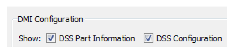
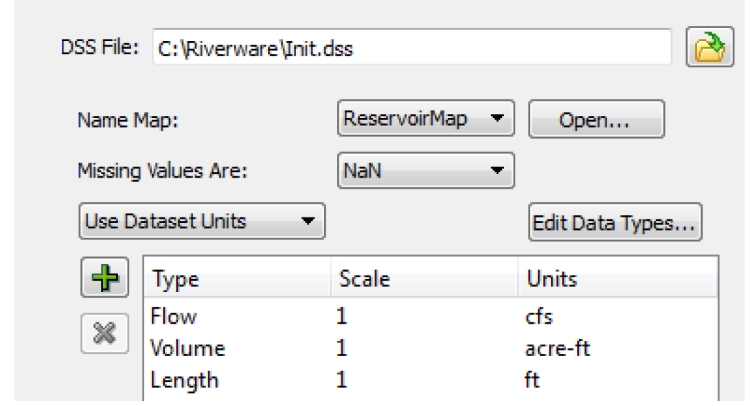
When there is a DSS dataset in the DMI, the DSS checkboxes are displayed. Select the DSS Configuration check box to show general configuration settings.
This shows a view similar to the dataset. When you have a DSS dataset selected, the general configuration becomes enabled and allows you to:
• Specify the DSS file for a DSS Dataset.
• Specify the name map using the pull down menu and/or Open the name map manager.
• Specify the missing value behavior for the selected DSS Dataset.
• Specify the units for the selected DSS Dataset.
• Configure Data Types by selecting the Edit Data Types button.
See “Datasets Overview” for descriptions of these fields.
Note: Each of these specifications only works on the selected dataset. In other words, you must highlight a dataset row from the middle portion of the dialog before it allows you to change units, scale, name map to use, or how missing values are treated.
Setting Multiple DSS Dataset Files
You can configure the DSS file path for multiple DSS datasets through the Configure DSS Datasets dialog. The dialog is opened by
• Right selecting a DSS dataset in the Database DMI editor dialog and selecting the Set Multiple DSS Dataset Files menu item, or
• Selecting a DSS dataset in the database DMI and then using the Datasets, then Set Multiple DSS Dataset Files menu.
The Configure DSS Datasets dialog appears.
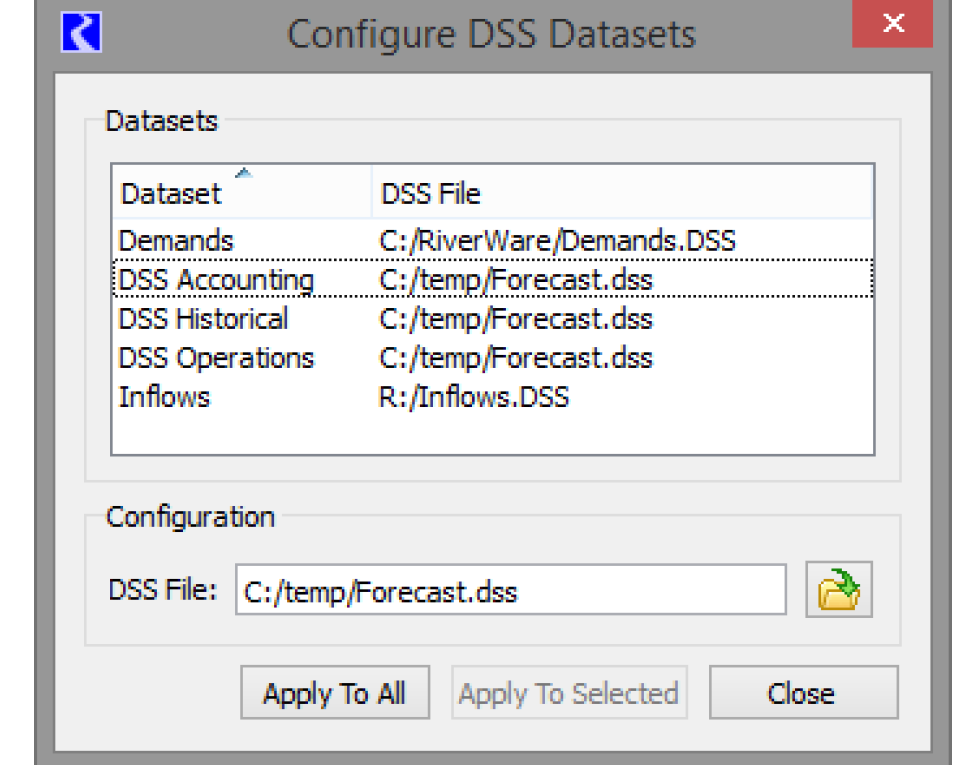
The top portion of the dialog shows all of the DSS Datasets in the model and their DSS File in sortable columns. The bottom portion of the dialog shows the file path for the dataset that was selected when the dialog opened.
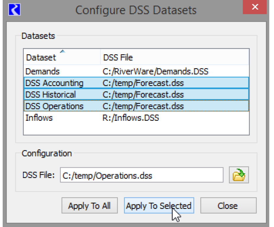
Specify an alternative DSS file if desired. Then:
• Select one or more datasets to modify and choose Apply to Selected as shown below.
• Select Apply to All to change every dataset to the new file path.
If a DSS dataset has been modified in another dialog, the DSS file cannot be set. You are notified with the following message: “The following datasets cannot be modified because they are being modified in another dialog”. Apply the changes to that dialog and you can now use the Configure DSS Datasets dialog again.
DSS DMI User Parameters
For DSS, you can specify values to be used for the user parameters. The parameters must be previously configured using the Parameter Dialog; see “DMI Parameter Dialog” for details.
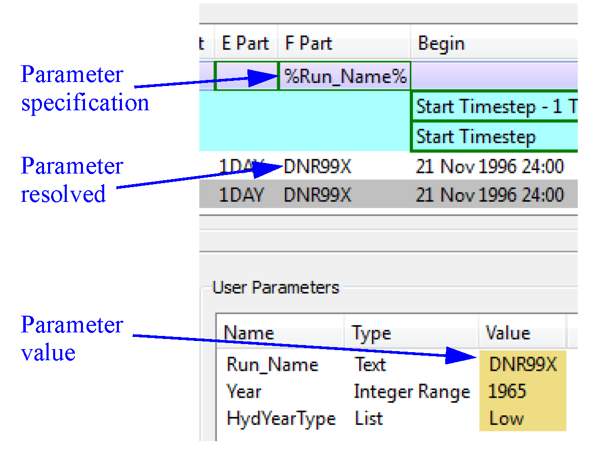
Edit a parameter value by double-clicking the Value cell to activate a control appropriate for the parameter’s type. To use the parameters in the DSS part information, specify the value with the percent sign; use the following syntax:
%Parameter%
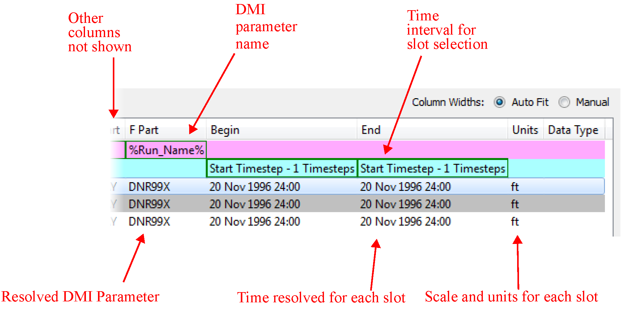
Thus if you have a parameter named Run_Name with a text value and you wanted to put the value in part F, you would double-click part F on the desired Dataset row and type %Run_Name%. In the lower portion, double-click the value column and specify the integer to use. The resolved information is shown for each slot that is a part of the dataset. Figure 4.9 shows this example.
Figure 4.9
Examples
Now that we have described the overall approach for creating a Database DMI, we will present a few example use cases of creating various types of Database DMIs.
Example 1: DSS DMI Using the Database DMI Editor
This example shows how to create a Database DMI to/from DSS using the Database DMI Editor. We assume there are no other Datasets or Name Maps already defined. You would take the following steps:
1. From the workspace, open the DMI Manager using the DMI, then DMI Manager.
2. Create a new Database DMI using the DMI, then New Database DMI menu.
3. Open the Database DMI Editor using the Edit, then Edit menu.
4. In the upper portion of the dialog, enter a name, whether it is an Input or Output DMI, whether to confirm warnings, and whether to record invocations; see “Name and Type”. Let’s assume we are creating an Output DMI. Leave everything else unchecked.
5. First, add a dataset using the Datasets, then New DSS Dataset menu.
6. Expand the Dataset column and double-click the Dataset0 name and edit it.
7. Next, we will select the slots that we wish to output, say all Reservoir.Storages and Reservoir.Outflows. In the middle portion of the window, right-click the dataset you added, then use the New Slot Selection. A row is added to the tree view below the dataset.
8. Double-click the word NONE to open the slot selector. Use the selector to choose Reservoir.Storage. Add another slot selection and select Reservoir.Outflow. See “Creating a Name Map of All Reservoir.Inflow Slots” in User Interface for an example of a similar selection.
9. For the Reservoir.Outflow row, specify the timestep by right-clicking once in the Begin field. Choose “Start timestep”. In the End column right-click once and choose “Finish timestep”. For the storage row, repeat and choose “Start Timestep - N” to “Finish Timestep”. Double-click the “N” in the Begin column and type “1” to specify 1 timestep.
10. On the dataset row, right-click in the B Part and select Workspace Entity. Choose <Parent>.
11. On the dataset row, right-click in the C Part and select Workspace Entity. Choose <Slot>.
12. Select the treeview symbol next to the Reservoir.Outflow row to see the exact slots you are going to output and all the part information, timestep, and units. We could change any of the part information by selecting the appropriate column on the Dataset row. For example, we could enter OBS for observed in part F by selecting that field on the dataset row and typing it.
13. Now configure the dataset. Select the dataset row. In the middle of the dialog, select the DSS Configuration toggle.
14. Specify the name of a DSS File in which to send the output either by typing it or using the selector. On an Input DMI, this file must already exist. On the Output DMI, it will be created if it does not exist.
15. If we have already configured a Name Map, we could select that we wanted to use it in the middle portion of the dialog; see “DSS Dataset Configuration”. A name map is created outside of this dialog; see “Name Mapping”. Because this is an Output DMI, we do not necessarily have to have a Name Map.
16. Now let’s specify the units to write. In the middle section, select the “+” button. Repeat to add two rows. See “DSS Dataset Configuration” for details.
17. Double-click the word NONE under the type column to activate the pull-down menu. Choose Volume. On the Units column repeat and choose the desired unit, say Acre-feet. On the second row, Choose Flow and cfs as the units.
18. The Database DMI is now fully configured. Select OK to close the dialog and apply the changes. Invoke the DMI from the DMI manager using the DMI, then Invoke menu.
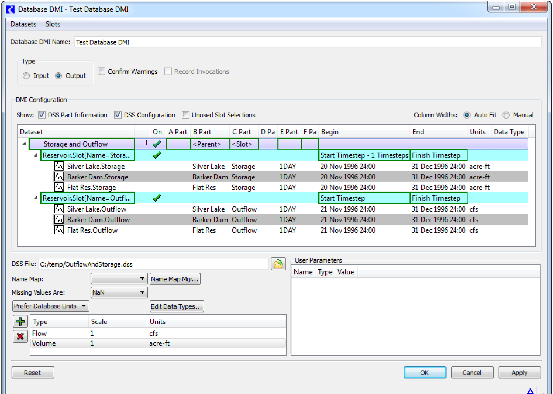
Figure 4.10 shows the configuration for this example.
Figure 4.10
Example 2: Excel DMI to Export Data Using Headers
This example shows how to create a Database DMI to export data to Excel using the Header approach. We assume there are no other Datasets or Name Maps already defined. You would take the following steps:
1. From the workspace, open the DMI Manager using the DMI, then DMI Manager.
2. Choose Utilities, then Datasets
3. Choose Dataset, then New Excel Dataset
4. Double-click the newly created dataset to open it.
5. You will create an output DMI so specify a name in the Name: field. Say “Excel Header PE Sheet”.
6. Select the Excel tab and type in or navigate to a worksheet. Because it is an output DMI and you don’t have an existing sheet, you will have to type in a file name in the selector.
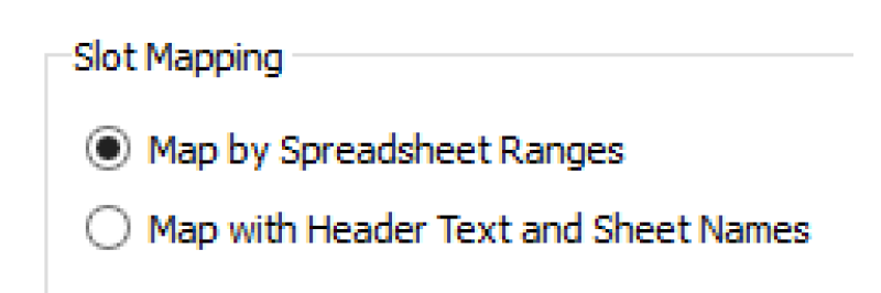
7. Now you will need to choose which approach you wish to use: Ranges or Headers. If you choose Ranges, you will need to create Name Maps. See “Slot Mapping—Spreadsheet Ranges Approach” for similar samples, based on the configuration. Let’s use the header approach (see “Slot Mapping—Header Text and Sheet Names Approach”). Select the Map with Header Text and Sheet Names option.
8. You are exporting series slot data, so select the Series Slots option.
9. Specify the Header orientation and specify a sheet name, for example PE. In this sample, use the Timestep, Slots, Runs option.
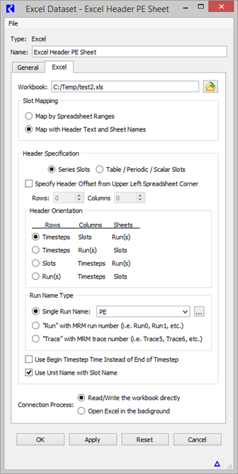
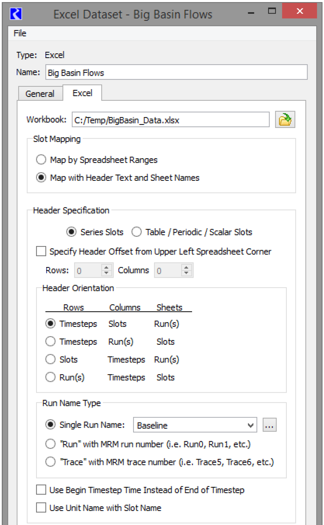
10. Optionally, specify to Use Unit Name with the Slot Name. Figure 4.11 shows the setup for the Excel tab. With this setup, you do not have to use Name Maps, but you could. Thus, we have a fully configured dataset.
Figure 4.11
11. Select OK to accept the changes and close the dialog
12. Back in the DMI Manager, create a new Database DMI using the DMI, then New Database DMI menu.
13. Open the Database DMI Editor using the Edit, then Edit menu.
14. In the upper portion of the dialog, enter a name, that it will be an Output DMI, and whether to confirm warnings. See “Name and Type” for details.
15. Now add the dataset you configured earlier. Choose Datasets, then Add Existing to open the Dataset Selector dialog.
16. Choose the “Excel Header PE Sheet” dataset and select OK.
17. Next, we will select the slots that we wish to output, say all Reservoir Pool Elevations. With the Excel Header PE Sheet row highlighted, use the Datasets, then New Slot Selection menu.
18. Double-click the word NONE to open the slot selector. Use the selector to choose all Reservoir.Pool Elevations. See “Creating a Name Map of All Reservoir.Inflow Slots” in User Interface for an example of a similar selection.
19. For the Reservoir.Pool Elevation row, specify the begin timestep by right-clicking once in the Begin field. Choose “Start timestep”. In the End column right-click once and choose “Finish timestep”.
Figure 4.12 shows this setup.
This database DMI is now fully configured. You can execute it from the DMI manager.
Figure 4.12
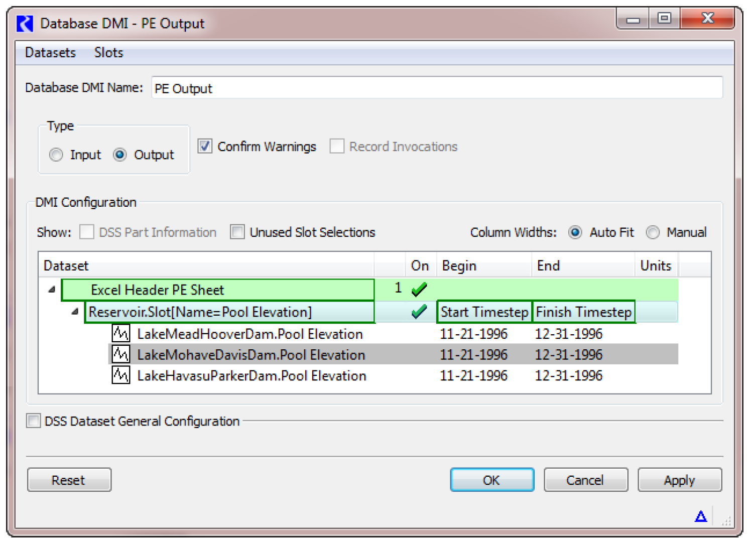
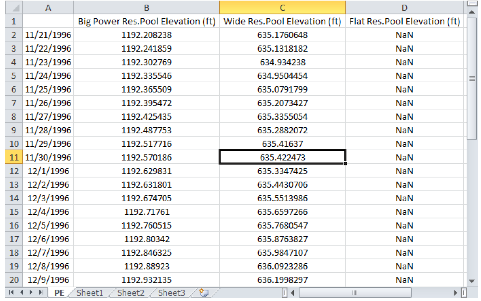
Figure 4.13 shows the resulting spreadsheet for our three-reservoir model.
Figure 4.13
Example 3: Excel DMI to Import Data Using Ranges
This example shows how to create a Database DMI to import data from Excel using the Ranges approach. We assume there are no other Datasets or Name Maps already defined. You would take the following steps:
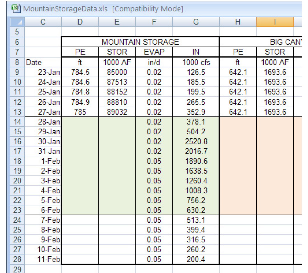
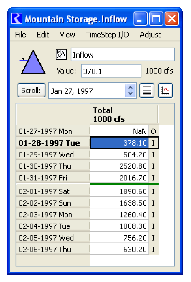
1. Figure 4.14 is screenshot of the desired data in Excel. It is not in the format necessary for the Headers approach. So we will use the Ranges approach. We would like to import the Mountain Storage IN column to the slot Mountain Storage.Inflow for just the run range (Jan 28-Feb 6th). That is, we want to import the range G14:G23.
Figure 4.14
2. From the workspace, open the DMI Manager using the DMI, then DMI Manager.
3. From the DMI Manager choose Utilities, then Name Maps.
4. Choose Name Map, then New or select the + button.
5. Double-click the newly created Name Map.
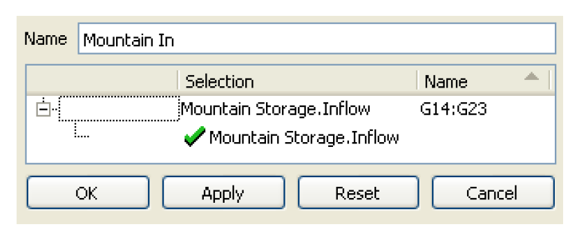
6. Change the name to “Mountain In”
7. Select Name Map, then New to add a row to the list.
8. Click-pause-click on the word NONE and choose Select Slot.
9. Using the selector, choose the reservoir slot Mountain Storage.Inflow. Select OK.
10. In the Name Map, in the Name column type “G14:G23” (without quotes).
11. Select OK in the Name Map and OK/Cancel in the Name Map Manager to close.
12. In the DMI Manager, choose Utilities, then Dataset.
13. Choose Dataset, then New Excel Dataset.
14. Double-click the newly created dataset to open it.
15. You will create an input DMI so specify a name in the Name: field: “Input Mountain Inflow”.
16. In the Name Map section, choose the Name Map you created “Mountain In” from the pull down menu.
17. Select Units, then New
18. Under the Type column, click-pause-click and choose Flow from the pull down menu.
19. Change the Scale to 1000 and the Units to cfs.
20. Select Apply.
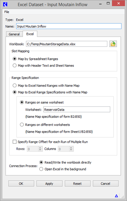
21. Select the Excel tab and type in or navigate to the worksheet where the data resides. In the sample, it is in C:/Temp/MountainStorageData.xls.
22. Select the Map by Spreadsheet Ranges button.
23. Choose the Map to Excel Range Specification with Name Map.
24. The data is all on the same worksheet and we didn’t enter it in the Name Map, so you will need to enter it here. In the Worksheet field, enter the name of the sheet, “ReservoirData”.
25. The dataset is fully configured, as shown in Figure 4.15. Select OK to apply and close the dialog.
Figure 4.15
26. Back in the DMI Manager, create a new Database DMI using the DMI, then New Database DMI menu.
27. Open the Database DMI Editor using the Edit, then Edit menu.
28. In the upper portion of the dialog, enter a name and that it will be an Input DMI. See “Name and Type” for details.
29. Now add the dataset you configured earlier. Choose Datasets, then Add Existing to open the Dataset Selector dialog.
30. Choose the Input Mountain Inflow dataset and select OK.
31. We will select the slots that we wish to input. With the Input Mountain Inflow row highlighted, select Datasets, then New Slot Selection menu.
32. Double-click on the word NONE to open the slot selector. Use the selector to choose Mountain Storage.Inflow.
33. For the Mountain Storage.Inflow row, specify the timestep by right-clicking once in the Begin field. Choose “Start timestep”. In the End column right-click once and choose “Finish timestep”.
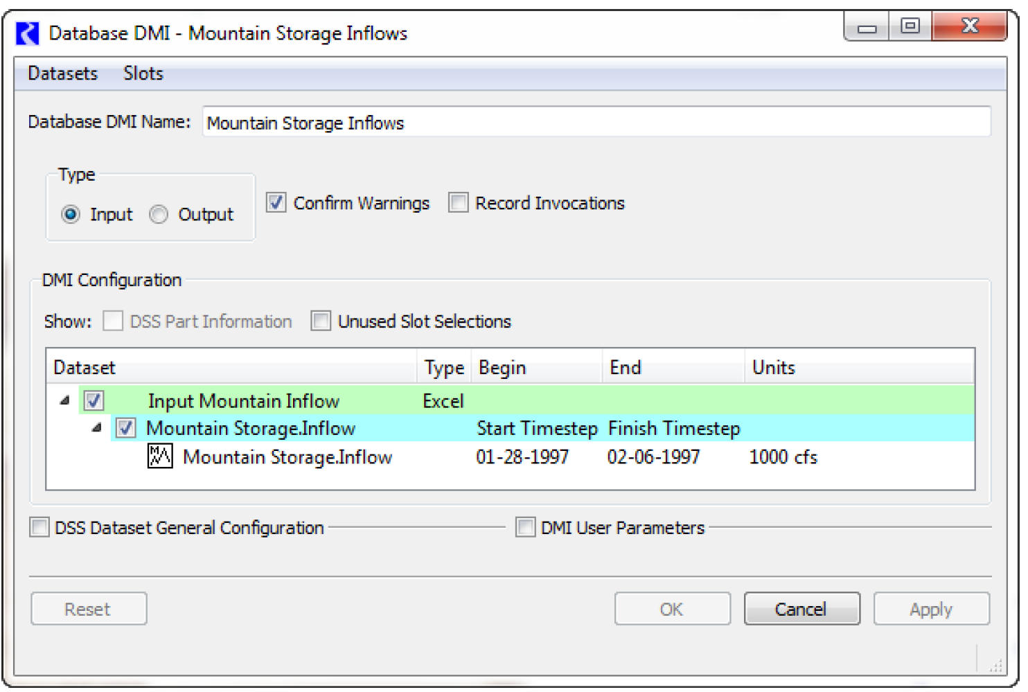
34. This database DMI is now fully configured. You can execute it from the DMI manager. Figure 4.16 shows the resulting slot.
Figure 4.16
Datasets Overview
A dataset encapsulates all RiverWare knowledge about the database. In general, there are two types of knowledge contained in a dataset, configuration information and the database specification.
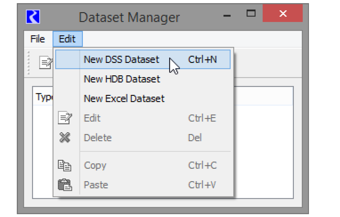
In RiverWare, datasets are defined and configured in the Dataset Manager as shown in Figure 4.17. The Dataset Manager is accessed from the Utilities, then Dataset menu on the DMI Manager. Selecting Edit, then New DSS Dataset, for example, adds a new DSS dataset.
Figure 4.17
DSS Datasets
In general, all of the DSS dataset configuration can (and should) be performed from the Database DMI Editor. The DSS Dataset editor shows the results of configuration but the Database DMI has much more functionality. This section describes the functionality of the Database DMI Editor with respect to DSS datasets.
Note: A DSS dataset must be selected for this area to become active.
DSS File
Specify the DSS file either by typing in the file path or selecting it using the open file icon  . If not already created, an export DMI will create the specified DSS file.
. If not already created, an export DMI will create the specified DSS file.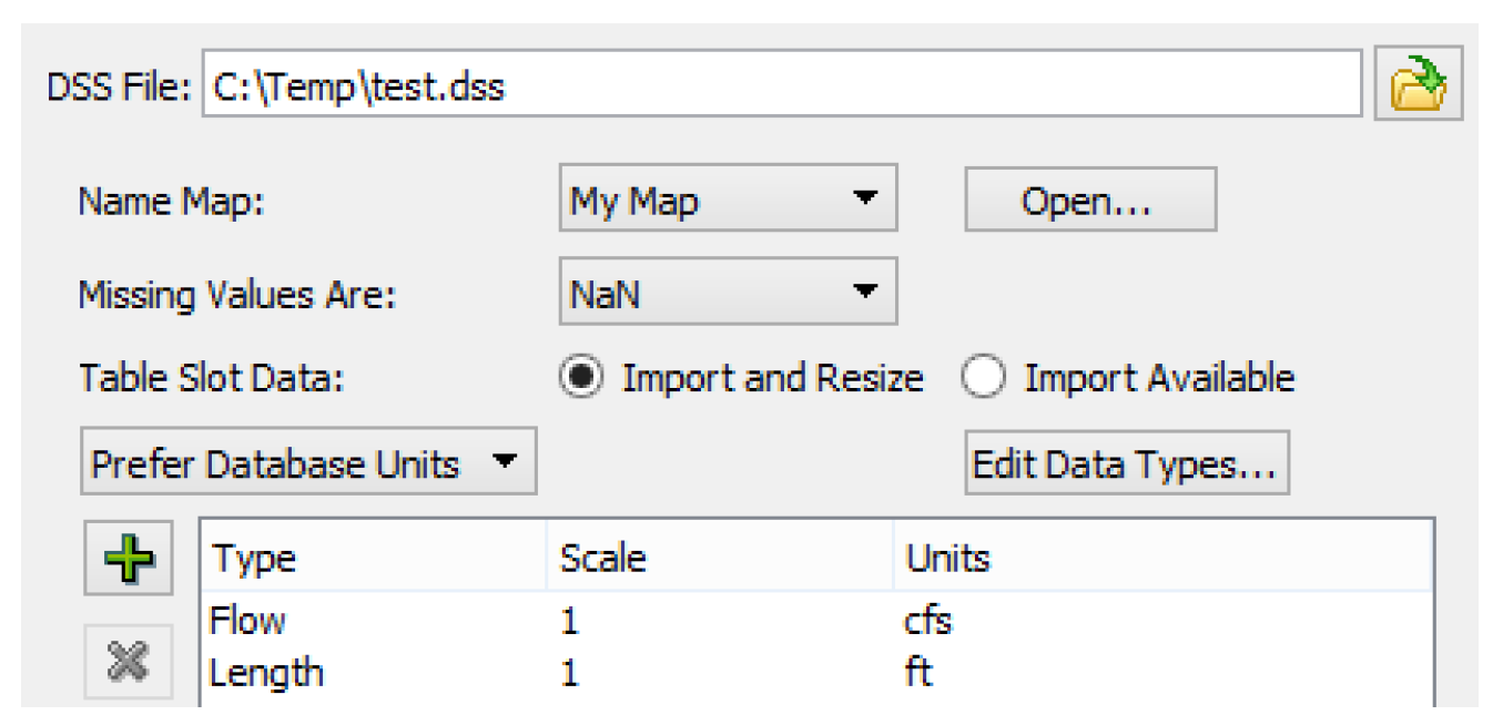
The DSS File name may contain user parameters as %ParamName% (the same as for the DSS part information). The DSS file name may contain multiple parameters but the parameters must be typed in; they are not available from a context menu. See “DSS DMI User Parameters” for details.
The DSS file name text shows the user parameters while a tooltip shows the substituted values.The user parameters can be all or part of the DSS file name and can be used in conjunction with environment variables, for example:
• A single parameter: %DssFile%
• A path and a parameter: C:\model\data\%DssFile%
• Multiple parameters: %ModelDir%\data\%DssFile% or %DataDir%\%DssFile%.dss
• Environment variable and a parameter: $(DATA_DIR)\%DssFile%.dss
Note: You can set the file path for multiple DSS Datasets in one action using the Configure DSS Datasets dialog; see “Setting Multiple DSS Dataset Files” for details.
Name Map
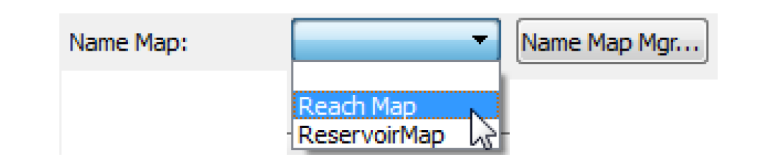
Optionally, select the desired Name Map from the Name Map menu. The selections are based on the Name Maps configured in the Name Map Manager. See “Name Mapping” for details on Name Maps. If you have no name map selected, select the Name Map Mgr button to open the Name Map Manager. If you do have a Name Map selected, the button says Open to open that Name Map.
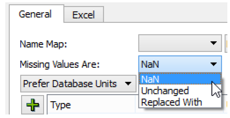
Missing Values
The user specifies how missing values are represented in the database. The current choices are
• NaN. RiverWare default, missing values are NaN in the database
• Unchanged. The DMI will not change missing values on import, uses NaNs on export
• Replace With. Provides a user input value that is substituted on import and export.
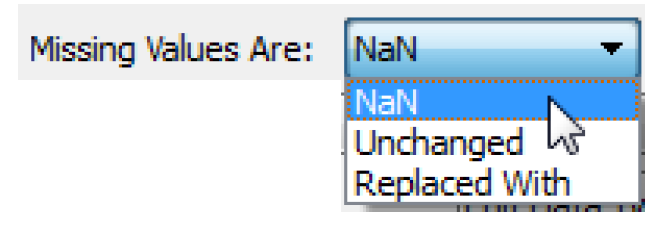
Table Slot Data
The user specifies how paired data should be imported to table slots in terms of overwriting existing data or leaving extra data unchanged.
This option is only enabled for Input DMIs. The options are:
• Import and Resize - a DSS DMI will import paired data by resizing the table to match the imported table. This is the default option. For example if the table slot currently has 20 rows, but the DSS data only contains 14 rows, then after import, the table slot will now have 14 rows. The 6 rows at the bottom of the table slot will be removed.
• Import Available - a DSS DMI will expand a table to accommodate the imported table but it won’t contract a table. This leaves any extra data in the table without change. For example if the table slot currently has 20 rows, but the DSS data only contains 14 rows, then 6 rows at the bottom of the table slot will remain unchanged. Only the first 14 rows will have the newly imported data.

Units
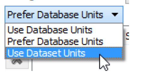
The units that are used in the DSS database are specified in the Dataset dialog. A pull-down menu allows the user to specify that the Database DMI should Use Database Units, Prefer Database Units, or Use Dataset Units. Figure 4.18 shows an example.
• Use Database Units. The database contains all units (This option is not applicable to DSS because units are not required to be defined in DSS files, so can’t be fully depended on)
• Prefer Database Units. Use the units in the database, if missing, use the specified Units
• Use Dataset Units. No units are specified in the database, use the specified units.
If you chooses either of the second two options, you must specify the units in the window below the pull-down menu. Select the  icon to add a new unit type:
icon to add a new unit type: This adds an entry to the list. Double-click the word NONE under the Type to change the type. Figure 4.18 illustrates. Change the Scale and Units in a similar manner. These units are used to specify the units that will be written to the database if an Output DMI is used and the units that the database contains if an Input DMI is used.
Figure 4.18
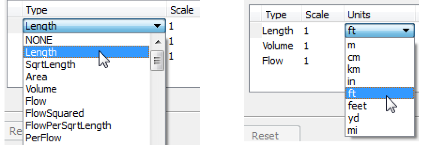
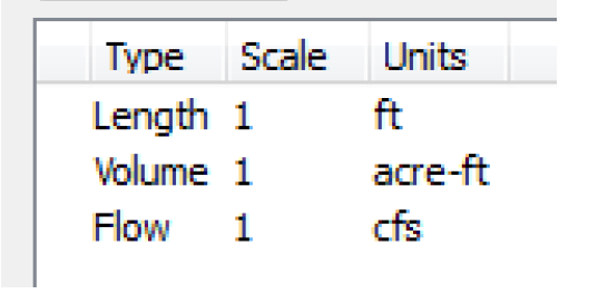
Figure 4.19 shows an example of specified units.
Figure 4.19
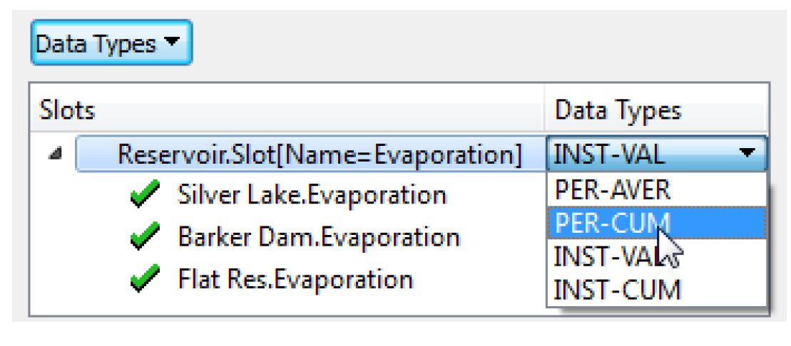
Data Types
Select the Edit Data Types button to edit the data types. In the resulting dialog, you can specify that a selection of slots should have a certain data type. The DSS data types are: PER-VAL, PER-AVER, INST-VAL, INST-CUM. The selection is similar to other slot selections as it is dynamic and can make full use of wildcarding.
HDB Datasets
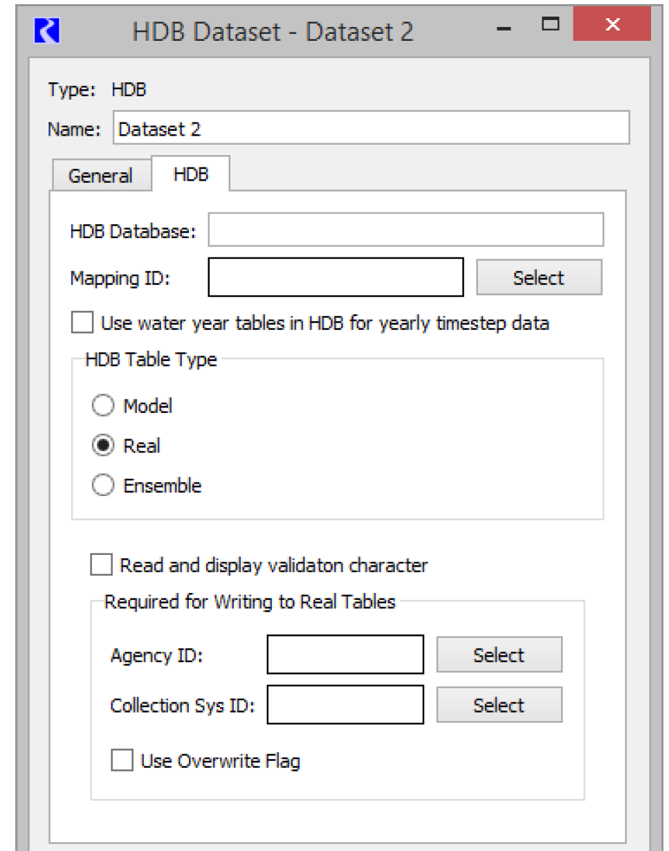
Double-clicking an HDB dataset in the Dataset Manager opens the HDB Dataset editor. In this dialog, the dataset can be renamed and configured. It has two tabs, one for general configuration and one specific to the HDB implementation.
General Tab
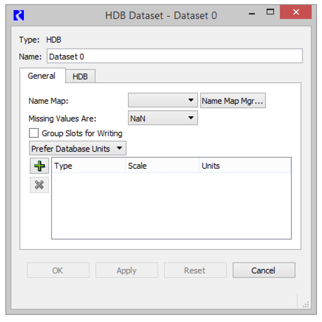
Name Map
Mappings of RiverWare names to HDB IDs are contained in database tables, so Name Maps are not needed for configuring a dataset for HDB. Specifying which database mapping to use is described later in the HDB tab of the configuration dialog.
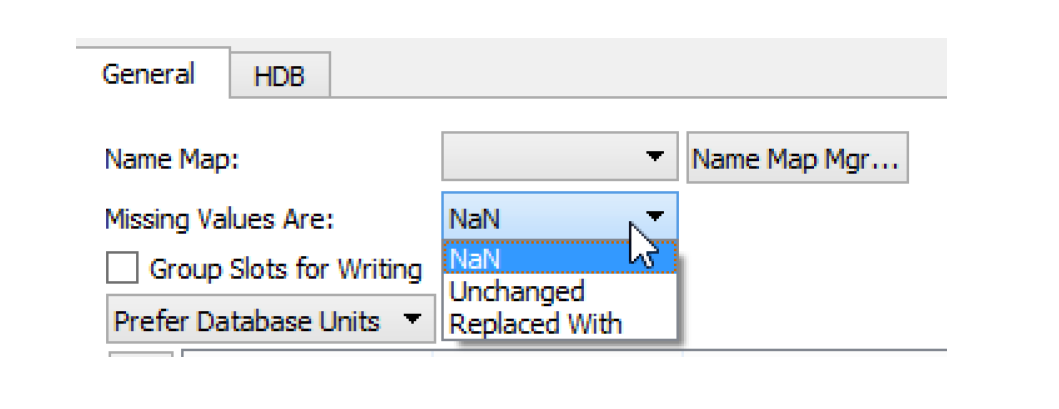
Missing Values
You specify how missing values are handled when exchanging data with HDB. In general, a NaN in RiverWare is not represented as a data record in HDB. The current choices are as follows:
• NaN. On export, no data record is created in HDB for NaNs in RiverWare, and any corresponding existing data record in the real tables is deleted (there would be no existing data record in the model tables). On import, missing values in HDB are made NaNs in RiverWare.
• Unchanged. On export, any existing data in the HDB real tables is left unchanged for a corresponding NaN value (there would be no existing data record in the model tables). On import, RiverWare data is left unchanged for a missing value in HDB.
• Replaced With. User provides an input value that is substituted for NaNs on export or missing values on import.
Group Slots for Writing
The Group Slots for Writing check box configures the DMI to group slots together when writing to the database. This option is particularly useful when you have many slots but few values in those slots. Grouping the slots minimizes the network traffic. This can significantly improve performance over a network.
Units
A menu in the Dataset dialog allows you to specify how units should be handled for a dataset. The choices are as follows:
• Use Database Units
• Prefer Database Units
• Use Dataset Units
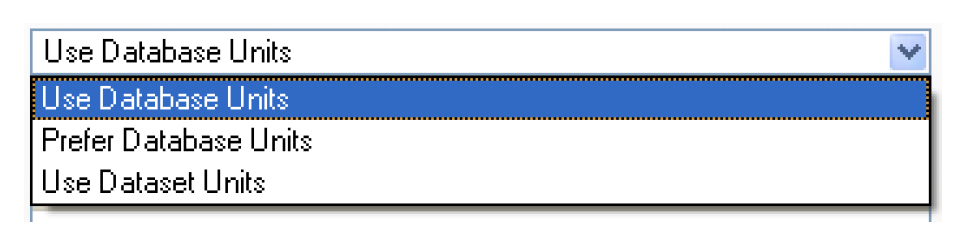
Units are defined in HDB for each piece of data, so Use Database Units is always applicable. If the unit type of the data in HDB does not match the unit type of the slot in RiverWare and the units cannot be converted, the slot is skipped and a warning message is given. The exception is if the unit type of the slot in RiverWare is NOUNITS. Here the unit type matching between HDB and RiverWare is skipped and the data is allowed to be exchanged with no conversions being applied.
In addition, to improve performance you can configure slot units in the Dataset and Use Dataset Units. This prevents additional calls across the network to get the units from the database.
Configuration specific to the HDB database is specified in the HDB tab of the HDB Dataset editor.
HDB Tab
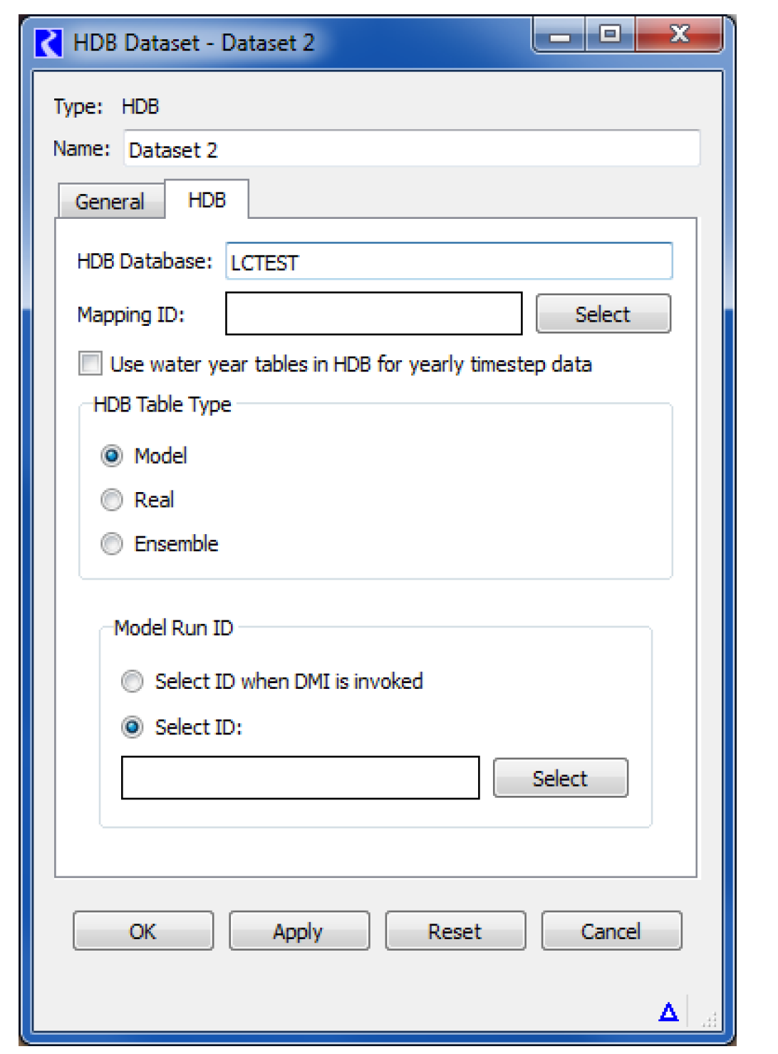
HDB Database
The HDB Database field specifies which database the dataset will interact with. The entry in this field should be a TNS name or connect string that will allow connection through Oracle Networking Services (SQL*Net) to the desired database. You need to have Oracle networking available on your computer through Oracle Client or a full Oracle database installation.
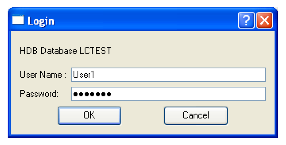
The first time in a RiverWare session that a specified database is connected to, you are prompted to provide a user name and password to log in. For a user to retrieve metadata or read and write data to HDB, they must be granted the roles model_priv_role and app_role in the database to have the necessary permissions.
To run in batch mode, the login information must be provided in a file. The code looks for a file named.dblogins in your home directory, which is specified by the HOME environment variable on Solaris, and the combination of the automatically defined HOMEDRIVE and HOMEPATH environment variables on Windows. The format of the file should be a line for every database, with that line containing the database name, login, and password separated by whitespace (blanks or tabs). Blank lines and comment lines starting with # are permitted in the file. If you want to set up a different file, the DBLOGINS environment variable can be defined as a full path (directory and file) where the code will look for the login information.
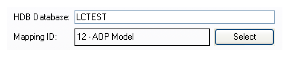
Mapping ID
The Mapping ID field specifies what mapping will be used in the database to map RiverWare objects and slots to HDB sites and data types. You must select the adjacent Select button to pick a mapping from the database.
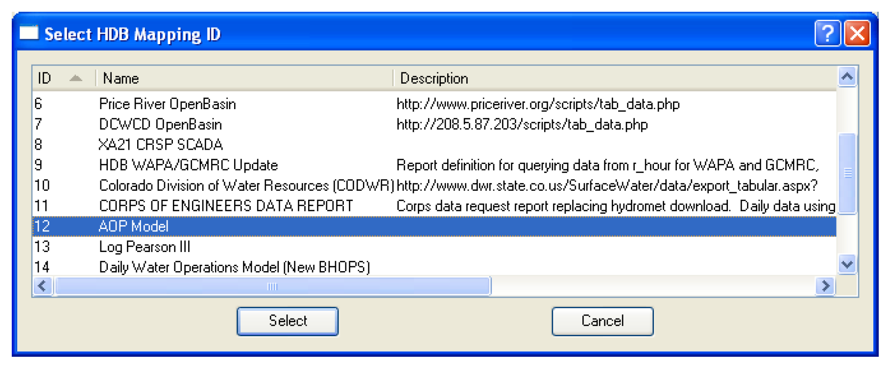
The Select button brings up the Select HDB Mapping ID dialog populated with all the available mapping IDs, their names, and descriptions from the HDB_EXT_DATA_SOURCE table in the database. You can then select a mapping, which populates the Mapping ID field on the HDB tab of the dataset dialog with the ID and the name of the mapping.
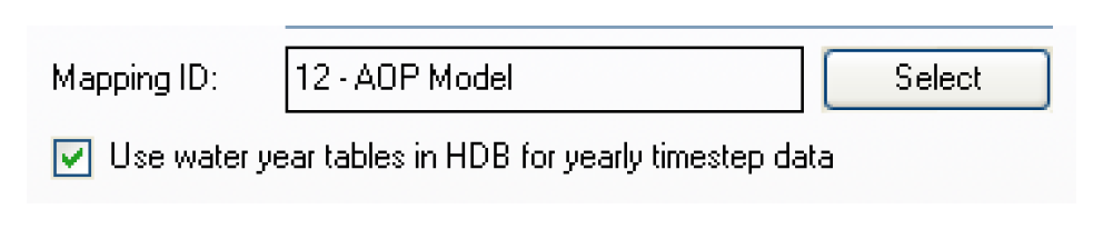
HDB maintains different tables for data of differing intervals (timesteps). Slots of varying timesteps can be freely intermixed in a list that is associated with a dataset, and the correct tables for each timestep will be automatically accessed in HDB. One case that does need specification is for the water year tables in HDB. There is no corresponding water year timestep in RiverWare, although some users have used slots with a 1 Year timestep to hold water year data in some of their RiverWare models. To handle this case, an option box on the dataset dialog to Use water year tables in HDB for 1 Year timestep data has been provided. If a user checks this box, all 1 Year timestep data read and written with the dataset will be moved to and from the water year tables in HDB instead of the year tables.
HDB Table Type
The HDB Table Type frame on the dataset dialog specifies which of the tables in HDB the dataset will interact with. The selection of Model, Real, or Ensemble determines the configuration options that become available in the rest of the dialog.
HDB Table Type—Model
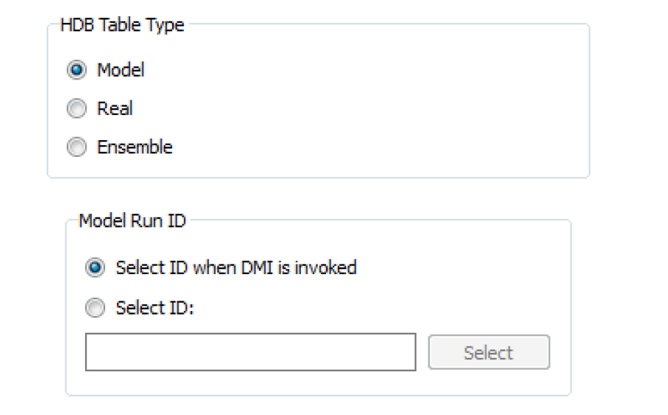
A selection of Model in the HDB Table Type frame of the dataset dialog means that any data moved using the dataset will be read from or written to the model (m_ xxxx) set of tables in HDB. Model data is typically forecasted data, although there are no restrictions on its dates being future or historic. There can be multiple forecasts made for a piece of data at the same date and time, so data in the model tables must be associated with a model run ID that indicates from what run of a model the data originated. If data is written to a model run ID with a DMI, any previous data that was associated with that ID will be deleted from the model tables. Therefore, only the data from one particular run of a model is represented in a single model run ID. Reading or writing of model data requires metadata selection in the Model Run ID frame that appears with the selection of Model in the dataset dialog.
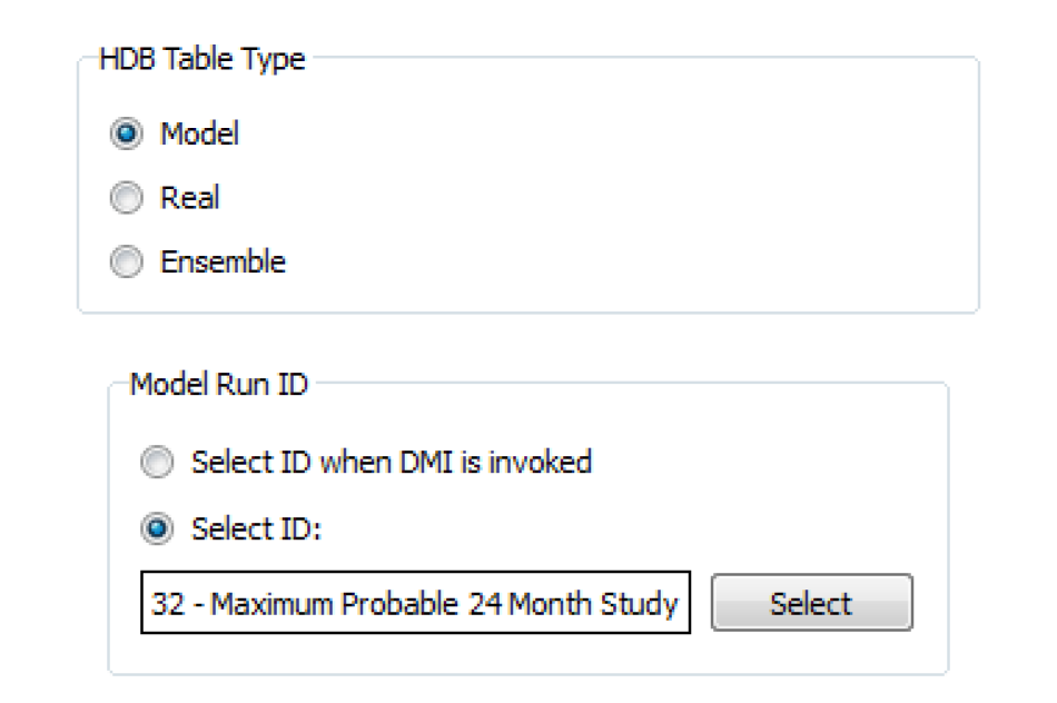
The Model Run ID frame allows you to select either Select ID or Select ID when DMI is invoked. The Select ID option allows you to preselect a model run ID to associate with the dataset for reading and writing data with the model tables. To select a model_run_id, you must select the Select button adjacent to the model run ID field. This brings up the Select HDB Model Run ID dialog.
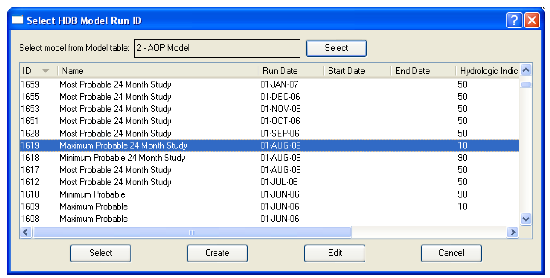
All model run IDs are associated with a particular model as defined in the database. The model run ID dialog is designed to display all the IDs in the database for a specified model. The model is selected via the Select model from MODEL table field at the top of the Model Run ID dialog. Selecting the Select button adjacent to the field brings up the Select HDB Model ID dialog populated with all the models defined in the HDB_MODEL table in the database.
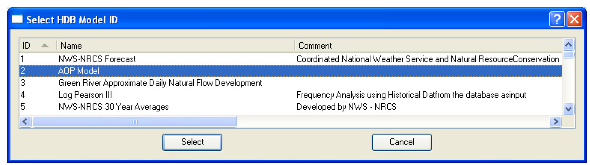
You can then select a model, which populates the Select model from MODEL table field on the model run ID dialog with the model ID and name, as well as populating the model_run_id list in the dialog with information for all the model_run_ids defined for the model. You can then select an existing model run ID from the list, which closes the dialog and populates the model run ID field in the Model Run ID frame of the dataset dialog with the model run ID and name.
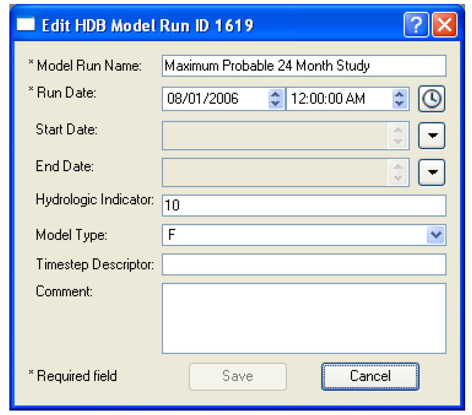
There are two other options for Model Run IDs on the Select HDB Model Run ID dialog. Instead of just selecting an existing ID, you can also edit an existing ID or create a new one. To edit or create a model run ID you still must have selected a model at the top of the dialog. An existing ID that is displayed can then be highlighted and edited by selecting the Edit button at the bottom. This brings up the Edit HDB Model Run ID dialog, which displays all the information fields for the model_run_id and allows you to edit these fields. Selecting the Save button will then save the edited information for this model run ID to the database.
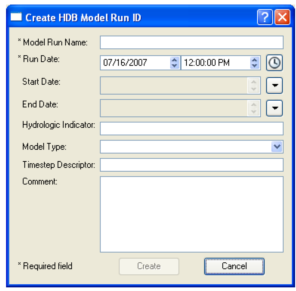
The Create button at the bottom of the Select HDB Model Run ID dialog allows you to create a model run ID that is associated with the model shown in the Select model from MODEL table field at the top of the dialog. Selecting Create brings up the Create HDB Model Run ID dialog, which contains fields where information can be entered for the new model run ID. The Run Date field is populated with the start time of the run, but can be changed by selecting any portion of the date and typing or using the spinners. At least the required fields marked with an asterisk must be filled out. Selecting the Create button will then save entered data to the database as a new model run ID where it will be assigned the next available model run ID number. The new ID will then be added to the list and highlighted back on the Select HDB Model Run ID dialog.
The Model Run ID frame of the dataset dialog has a second option for specifying model run IDs by selecting Select ID when DMI is invoked. When this option is selected, you do not preselect a model run ID that is always used with the dataset, but rather you are prompted for one when a DMI containing the dataset is executed. This option could be useful in a case where the DMI is run to record forecast data on a regular basis with the data always being preserved in separate model run IDs in the model tables. To limit the potential for you to accidentally overwrite the previously saved data by forgetting to change the ID; you must select the ID each time the DMI is run.
Selecting an ID under the Select ID when DMI is invoked option utilizes the same dialogs as does the preselect ID option. The Select HDB Model Run ID dialog appears where you can select a model and see its existing IDs. An existing ID can then be selected, an existing ID can be edited and then selected, or a new model run ID for the model can be created then selected.
Note: If the same dataset is used multiple times in a DMI, you are only prompted once to associate a model run ID with the dataset; the same dataset cannot be used with multiple model run IDs in a single DMI or DMI group execution.
HDB Table Type—Real
A selection of Real in the Table Type frame means that any data moved using the dataset will be read from or written to the real (r_ xxxx) set of tables in HDB. Real data are typically current or historical observed values; future data cannot be loaded into the real tables. A write of real data to HDB requires that some other metadata be selected by you in the Real frame that appears with the selection of a Real table type in the Dataset dialog.
Validation Characters
HDB has a per-value Validation field in the R_DAY, R_HOUR and R_INSTANT tables which typically indicates whether the data is provisional or approved. The field is a 1 byte character which is usually a “P” for provisional and an “A” for approved.
The Read and display validation character option allows you to import validation characters from HDB into Notes on Series Slot, which are then shown on slot and SCT dialogs. The Notes Manager dialog enables you to easily see all slots and timesteps with a particular note, for example to easily see all provisional slots and timesteps. See “Notes on Series Slots” in User Interface for details on Notes.
When the Read and display validation character is checked, the Validation field values are also imported through the DMI and set on a Series Slot Note, associated with the particular slot and timestep. The Series Slot Note Group which holds the validation characters is named “HDB Validation Group”. The group's name is fixed; you can't edit it. In the Edit Note Group, the label above the name is Fixed Note Group Name and the name is read-only. You can edit the group's color.
Required For Writing to Real Tables
The remainder of the controls for the Real table type are described in this topic.
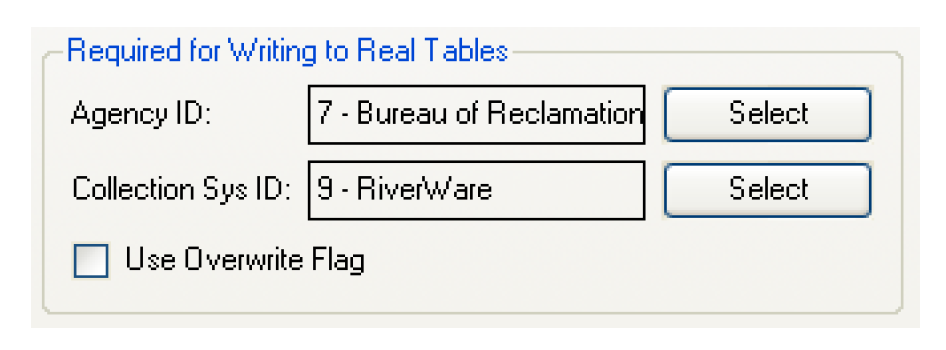
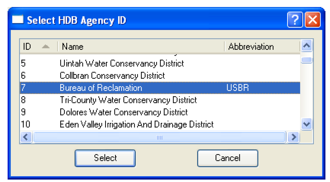
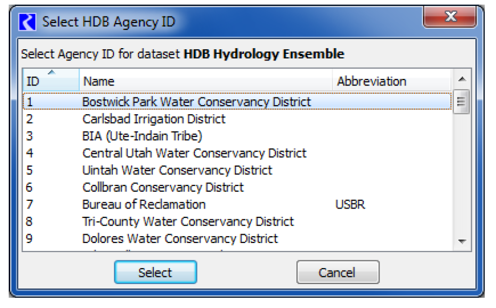
The Agency ID field specifies what agency ID will be associated with the data when it is written to the real tables. You must select an agency ID by selecting the Select button adjacent to the field. This will bring up the Select HDB Agency ID dialog populated with all the available agency IDs, their names, and abbreviations from the HDB_AGEN table in the database. You can then select an agency, which populates the Agency ID field on the dataset dialog with the ID and name of the agency.
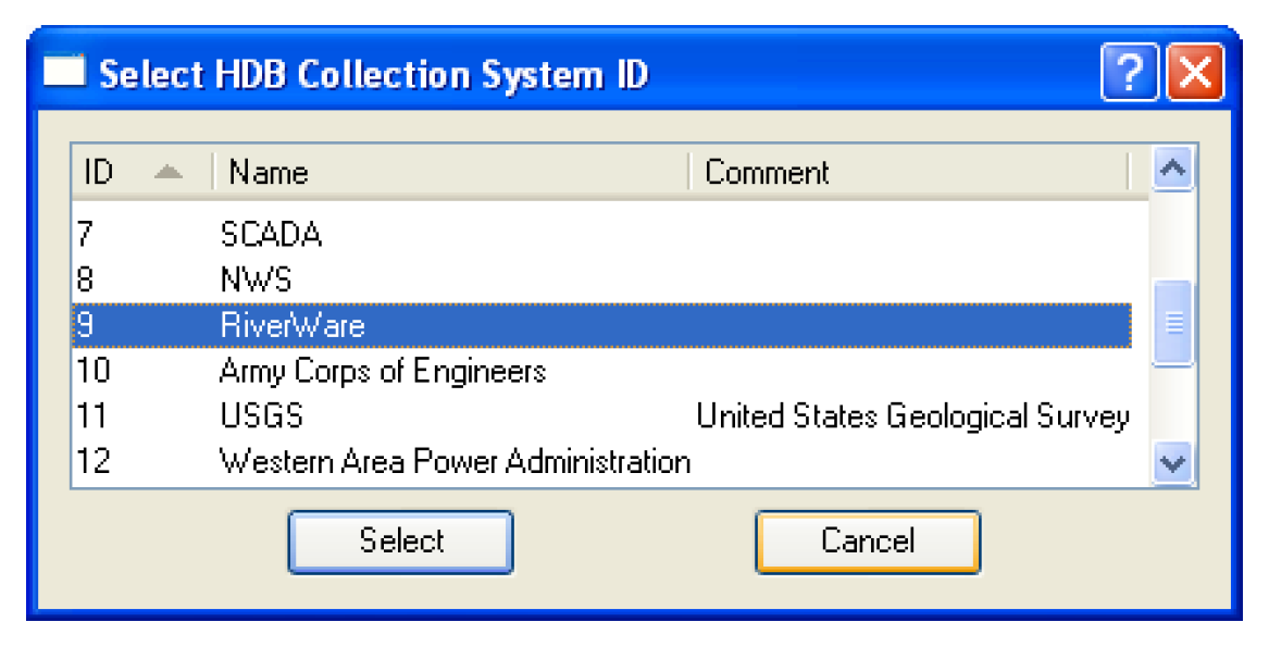
The Collection Sys ID field specifies what collection system ID will be associated with the data when it is written to the real tables. You must select a collection system ID by selecting the Select button adjacent to the field. This will bring up the Select HDB Collection System ID dialog populated with all the available collection system IDs, their names, and comments from the HDB_COLLECTION _SYSTEM table in HDB. You can then select a collection system, which populates the Collection Sys ID field on the dataset dialog with the ID and name of the collection system.
The Use Overwrite Flag check box specifies whether or not data is written to the real tables with an overwrite flag. This flag has some special meaning for how the data is handled in the database, namely that when the value is written to its real table, it cannot be overwritten by aggregations of data from a shorter interval. Normally this box would not be checked.
HDB Table Type—Ensembles
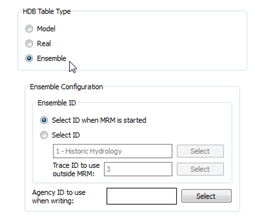
A selection of Ensemble in the Table Type frame means that any data moved using the dataset will be determined through the REF_ENSEMBLE table in the database. An ensemble has a number of traces associated with it, and each trace has an associated model run ID. An ensemble would be used with MRM so that each run of the multiple run would correspond to a trace in the ensemble, and the data for that trace would reside under the trace’s model run ID in the model (m_ xxxx) set of tables in HDB. See “Ensemble Configuration” in Solution Approaches for details.
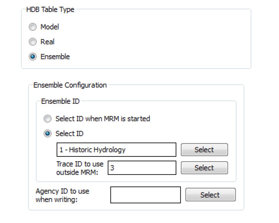
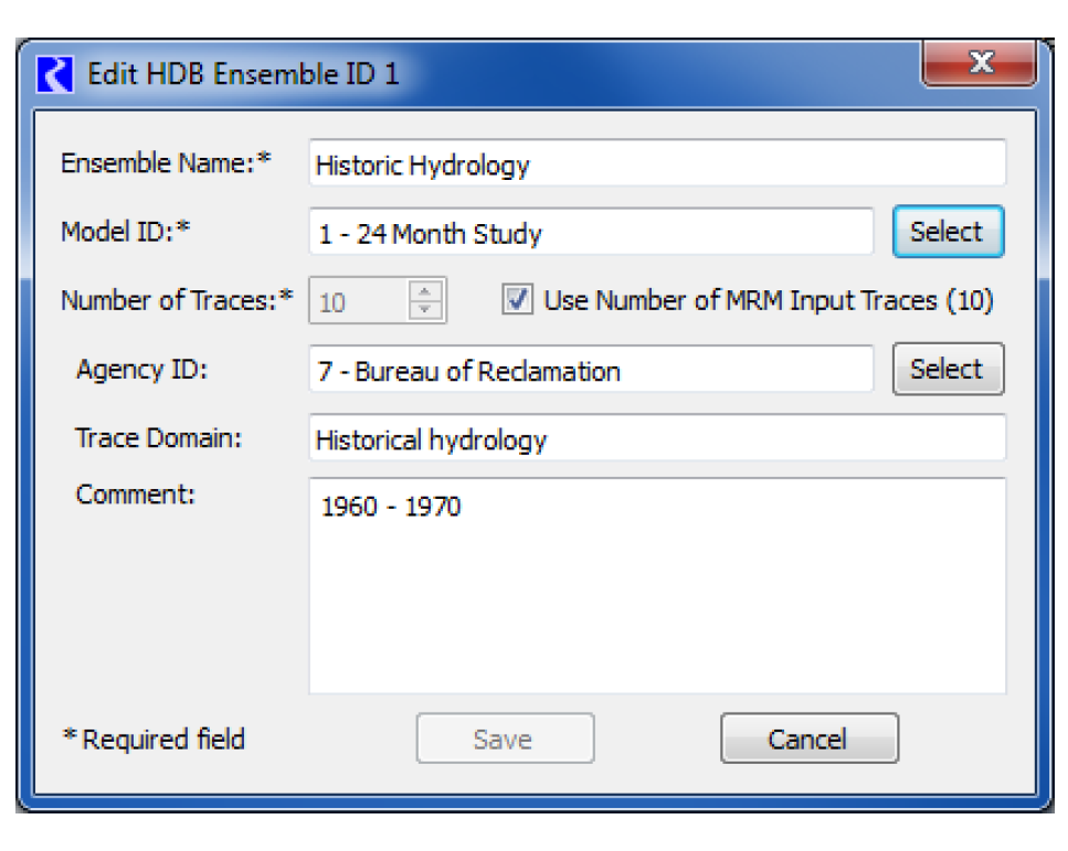
The Ensemble ID frame has options for you to Select ID or Select ID when MRM is started. The Select ID option allows you to preselect an ensemble ID to associate with the dataset for reading or writing data with the model tables. You must select an ensemble ID by selecting the Select button adjacent to the ensemble field. This will bring up the Select HDB Ensemble ID dialog populated with all the available ensemble IDs, their names, the agency, the domain for the traces, and comments from the REF_ENSEMBLE table in the database. You can then select an ensemble, which populates the Ensemble ID field on the dataset dialog with the ID and name of the ensemble.
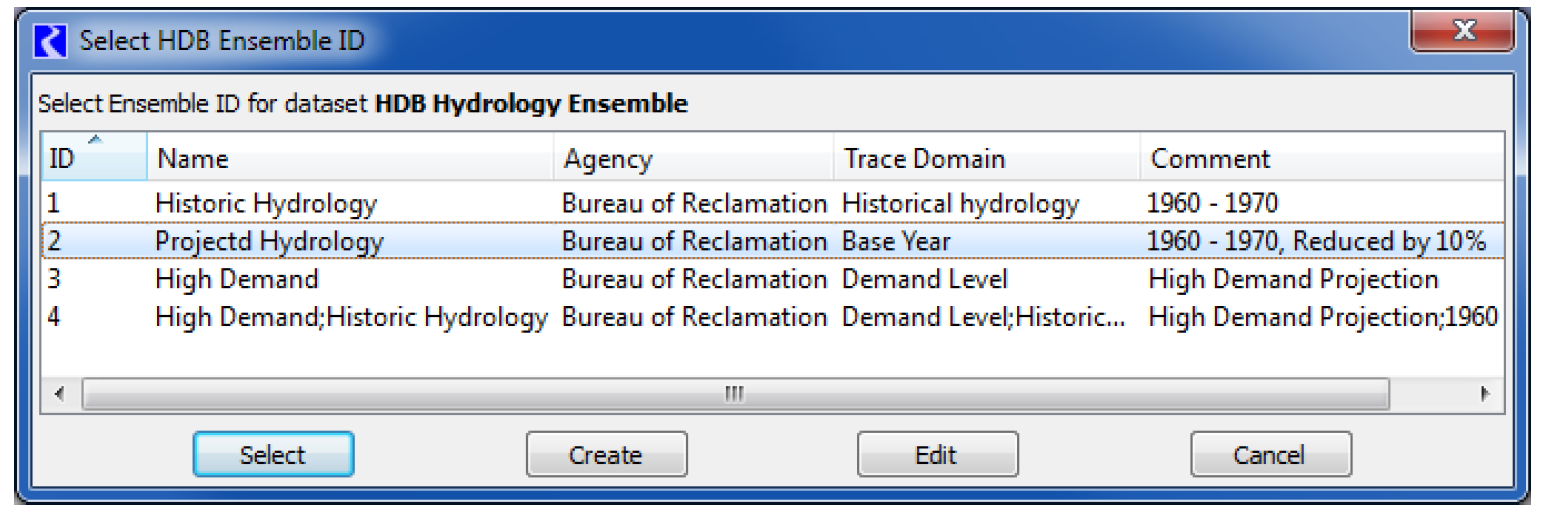
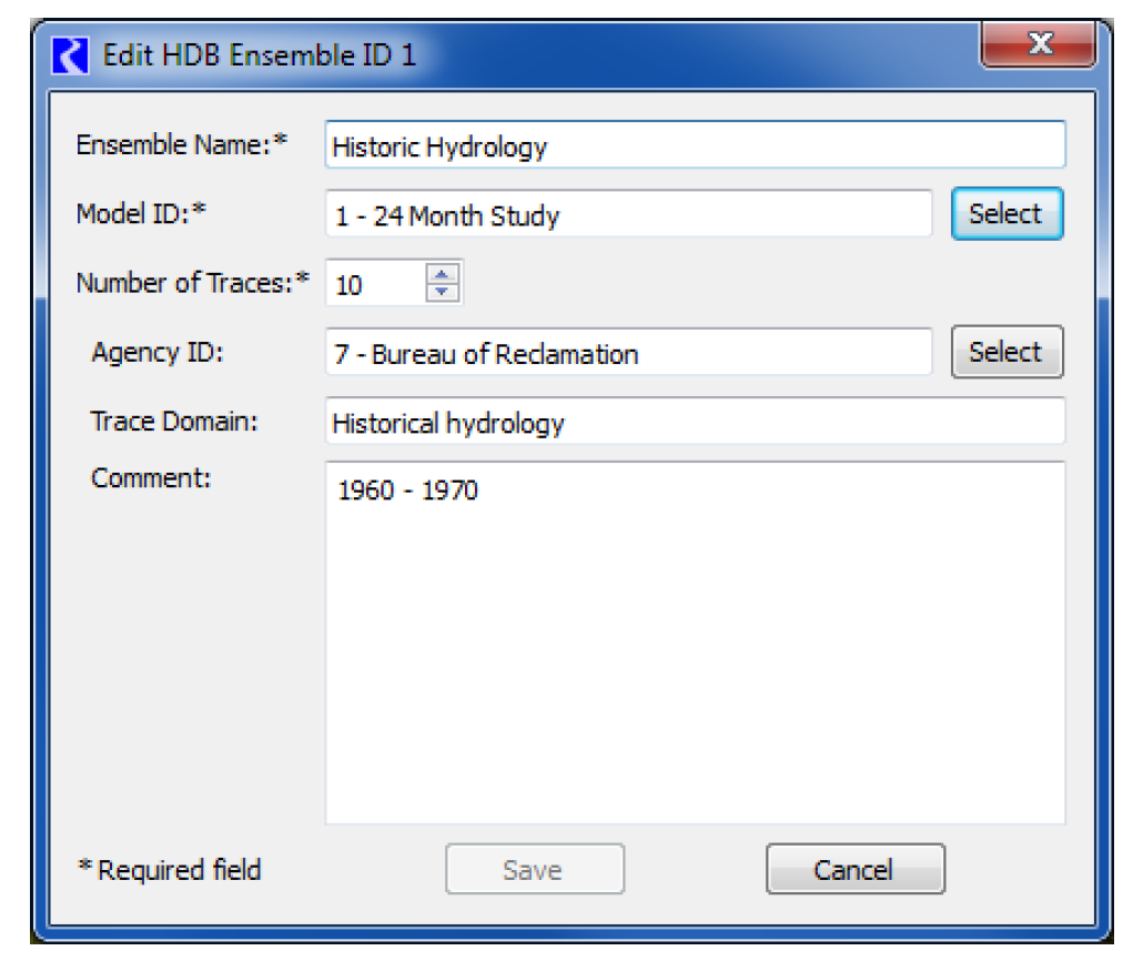
There are two other options for ensemble IDs on the Select HDB Ensemble ID dialog. Instead of just selecting an existing ID, you can also edit an existing ID or create a new one. An existing ID that is displayed can be highlighted and edited by selecting the Edit button at the bottom. This brings up the Edit HDB Ensemble ID dialog, which displays all the information fields for the ensemble id and allows you to edit these fields. Selecting the Save button will then save the edited information for this ensemble ID to the database.
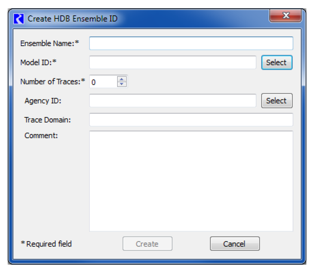
The Create button at the bottom of the Select HDB Ensemble ID dialog allows you to create an ensemble ID. Selecting this brings up the Create HDB Ensemble ID dialog, which contains fields where information can be entered for the new ensemble ID. At least the required fields marked with an asterisk must be filled out. Selecting the Create button at the bottom will then save entered data to the database as a new ensemble ID. The new ID will then be added to the list and highlighted back on the Select HDB Ensemble ID dialog.
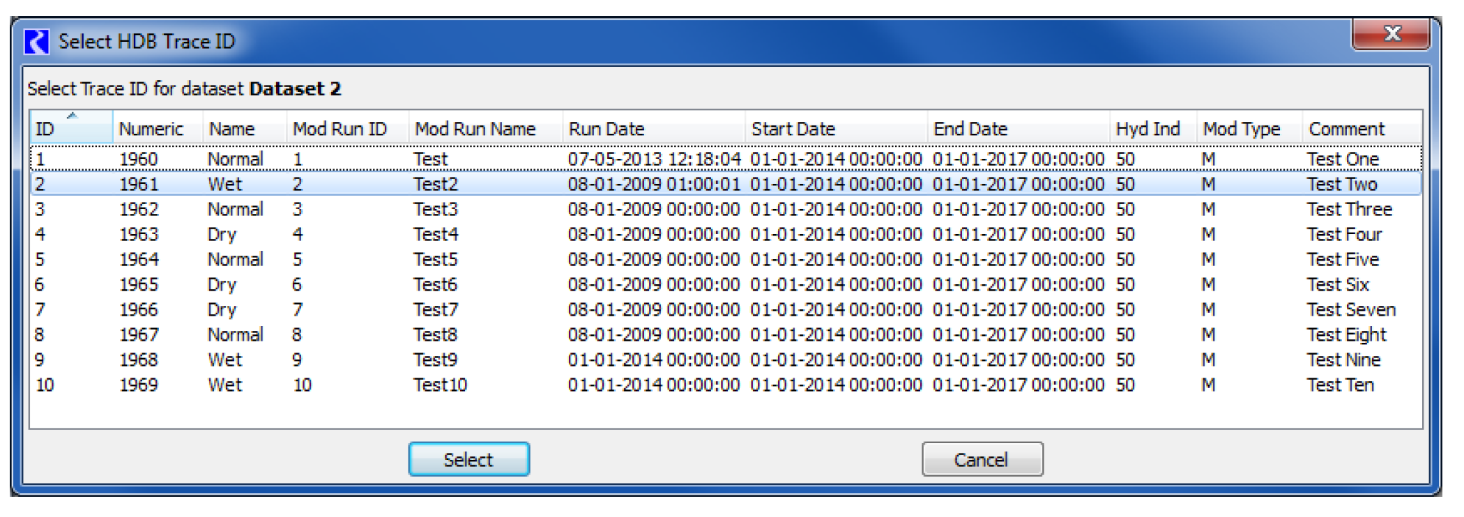
It may be convenient to use an ensemble dataset outside of a multiple run to pull a particular trace from the ensemble for use in a single run or to manually test a DMI. Selecting the Select button adjacent to the Trace ID to Use Outside MRM field will open the Select HDB Trace ID dialog that is populated with all the traces for your selected ensemble ID specified for the dataset. The dialog shows descriptive information for each trace from the REF_ENSEMBLE_TRACE table and also information for the trace’s model run ID from the REF_MODEL_RUN table. You can then select a trace, which populates the trace ID into the dataset dialog.
The Ensemble ID frame of the dataset dialog has a second option for specifying ensemble IDs by selecting Select ID when MRM is started. When this option is selected, you do not preselect an ensemble ID that is always used with the dataset, but rather you are prompted for one when an MRM run containing this dataset in an input or output ensemble is started. This option could be useful, for example, where you want to select a different output ensemble for each execution of the multiple run so that data from earlier runs is not overwritten.
Selecting an ID under the Select ID when MRM is started option utilizes the same dialogs as does the preselect ID option. The Select HDB Ensemble dialog appears when you start the multiple run where you can see existing ensemble IDs. An existing ID can then be selected, an existing ID can be edited and then selected, or a new ensemble ID for can be created then selected.
Note: If an ensemble id is being chosen for an output ensemble, the edit and create ensemble dialogs in this case have an additional trace control to Use Number of MRM Input Traces (xx), where xx indicates that number of traces. This provides an easy way for the edited or newly created output ensemble to contain the correct number of traces to hold the run data as defined by the input ensembles.
In addition to the ensemble id options discussed above, there is also an option under the Ensemble Configuration frame to select an Agency ID to use when writing. Selecting Select will open the Select HDB Agency ID dialog where one of the agency ids defined in HDB can be chosen. If chosen, that agency id will be written to the dataset’s ensemble when that dataset is executed as part of an output ensemble. If one is not chosen, the behavior will be to preserve any agency id that is already defined in the database for the output ensemble.
An HDB ensemble can have metadata that describe the ensemble as well as metadata that describe each trace. Metadata is a keyword associated with a value, such as “comment”/”Historic Hydrology”. In the HDB database, values for the “domain”, and “comment” keywords are held in the trace_domain, and cmmt fields of the REF_ENSEMBLE table. Other keyword/value pairs to describe ensembles are held in the REF_ENSEMBLE_KEYVAL table.
For trace metadata, the values for the “name” and “numeric” keywords are held in the trace_name and trace_numeric fields of the REF_ENSEMBLE_TRACE table. Other keywords to describe traces are held in the REF_MODEL_RUN_KEYVAL table.
See “Ensemble Configuration” in Solution Approaches for details on using Ensembles in MRM.
Excel Datasets
Excel datasets provide user configuration options to specify how you wish the Database DMI to work with Microsoft Excel. Excel datasets can only be used on the Windows platform and Excel must be available on the system. RiverWare will start a non-visible copy of Excel in the background and access the specified workbook during DMI execution. As a result, there are two important things to remember:
Note: You should not have the specified workbook open in a different copy of Excel as this may lock out RiverWare from accessing the workbook.
Note: RiverWare is operating on the Excel file, so you will not see any unsaved changes to the file that may be made in a different Excel session.
See “Example 2: Excel DMI to Export Data Using Headers” for a use case of creating a DMI to Excel.
General Tab
Double-clicking an Excel dataset in the Dataset Manager opens the Excel Dataset editor. In this dialog, the dataset can be renamed and configured. It has two tabs, one for general configuration and one specific to the Excel implementation. Following is a description of the configuration options.
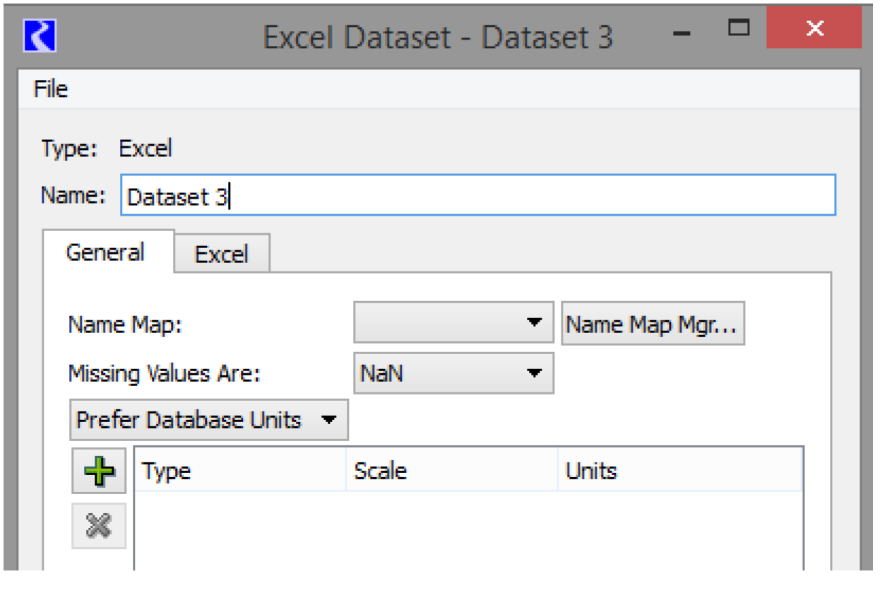
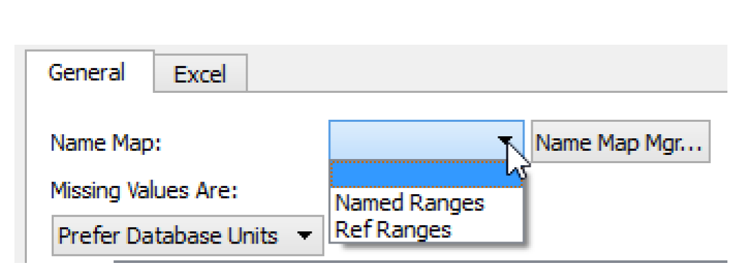
Name Map
Select the desired Name Map from the Name Map menu. The selections are populated based on the Name Maps configured in the Name Map Manager. See “Name Mapping” for details on creating Name Maps. Name maps have special relevance for moving data using range specifications and header specification. See “Slot Mapping—Spreadsheet Ranges Approach” and “Using Name Maps” for details.
Missing Values
The user specifies how missing values are handled with Excel. The current choices are
• NaN. NaN value in RiverWare is written as NaN to Excel, NaN or blank value in Excel is read as NaN into RiverWare
• Unchanged. The DMI will not change missing values on import, uses NaNs on export
• Replaced With. Provides a user input value that is substituted on import and export
Units
The units that are used in interacting with Excel are specified in the Dataset dialog. A pull-down menu allows the user to specify that the Database DMI should Use Database Units, Prefer Database Units, or Use Dataset Units.
• Use Database Units. Since Excel contains no units associated with a value in a cell, the slots’ units (i.e. from the Unit Scheme) as displayed in RiverWare are substituted for Database Units and will be used for import and export under this option
• Prefer Database Units. For Excel, this option uses the slots’ units (i.e. from the Unit Scheme) in RiverWare unless a unit is specified in the Dataset, then the specified unit is used
• Use Dataset Units: Uses the units specified in the dataset only
See “Units” for instructions on specifying the units to use.
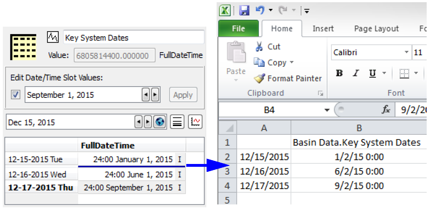
Note: For import and export of series slots that have the DateTime unit type, the DMIs translate to and from the Excel date representation. This allows dates to display correctly in both RiverWare and in Excel. But, Days/months/years in RiverWare are at the end of the timestep, which would be represented in Excel at the beginning of the next timestep. For example 24:00 June 1, 2015 in RiverWare would translate to 00:00 June 2, 2015 in Excel. Also, partial datetimes and dates before 1900 are negative values in Excel, so are just displayed with # signs as out of range. However the representation is still consistent and these date values will round trip correctly when exported to Excel and imported back into RiverWare.
.
Note: Text Series Slot values can be imported or exported using Excel Datasets and Database DMIs. These behave just like series slots but import or export the text strings. Be aware that a NaN in Excel will be interpreted as a string, not as an invalid value. Use blank cells in Excel to prevent importing NaN text strings. See “Text Series Slots” in User Interface for details.
Excel Tab
Configuration specific to Excel is specified in the Excel tab of the Excel Dataset editor.
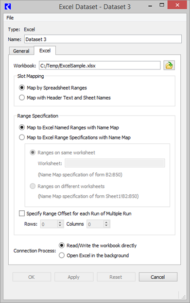
Workbook
In all cases, the Workbook that the dataset will read data from or write data to must be specified. The path and workbook name can be typed into the Workbook text box, or you can select the adjacent button to select the file. When executing an input DMI, this workbook must already exist. For an output DMI, the workbook will be created if it does not already exist.
Slot Mapping
Two approaches are provided for mapping data between RiverWare and Excel.
• Ranges: Specify the Excel range for each RiverWare slot. Choose the Map by Spreadsheet Ranges approach,
• Headers: Use a row header, a column header, and a worksheet name to map the Excel data with a RiverWare slot. The Map by Header Text and Sheet Name approach.
Table 4.3 compares these approaches. Then more information is presented on the configuration options for both the Range and Header approach.
Question | Ranges Approach | Headers Approach |
|---|---|---|
What is the format of the Excel data? | Your data is in any format in Excel, but you must then specify how the data maps to RiverWare slots. | Your data in Excel has row header names, column header names, and sheet names that identify the data in a way that matches one of the orientations in the dataset. |
How is the data mapped? | A DMI Name Nap specifies how the data in RiverWare slots “maps” to data in an Excel sheet. Name Maps can specify an Excel absolute cell reference (A1:A23) or a named range. | The text in header cells in Excel and the name of the sheet “map” the data to RiverWare slots. |
Can I have more timesteps of data in Excel than I want to import/export? | Yes, but the mapped Excel range must match the number of timesteps specified in the DMI. That is, the size of the range you specify must exactly match the number of values in the DMI. | Because this approach includes timestep information, the Excel sheet can have more data in it than you are processing via the DMI |
Can I import and export table, periodic, or scalar slots? | Yes, your named ranges or cell references can map to non-series data. | Yes, a dataset using the Header approach can either deal with Series slots OR Table, Periodic or Scalar slots, but not both at the same time. |
Can or do I use Name Maps? | You must use name maps to specify where the data will import from/export to in Excel. | Name Maps can optionally allow you to have different names of objects or slots in RiverWare than the header text in Excel. |
How are MRM runs handled? | Data for each MRM run is offset from the previous run by a certain number of rows and columns, starting with the mapped range. | MRM runs is one of the variables you specify in the Excel orientation. MRM runs can be on sheets, columns or rows. Their names can optionally be Run0, Run1, Run2, etc. or trace number as set up in the MRM configuration (i.e. Trace5, Trace6, Trace 7, etc.) |
How do I specify the Excel sheet? | Either specify a single sheet name or include the sheet name in the Name Map. | Sheet names depend on the selected orientation and can be run, slot, or timestep names. |
What is the format of the timestep in Excel? | No timestep information is read or written. | You specify to either use the end of timestep (E.g. Jan, 1, 2011 23:59) or the beginning of timestep format (E.g. Jan 1, 2011 0:00). |
How do I specify the units for Excel? | No unit information is read or written. Units in Excel are assumed to be the slot’s units in RiverWare (i.e. from the active Unit Scheme). The General tab of the dataset can be used to specify a mapped unit by type if the units in Excel are different than the RiverWare slot units. | You can optionally write the unit name with the slot name to Excel or can read a slot name from Excel if it has a unit name with it. However the assumed units for values and the possibility for mapped units work the same as in the Range approach. |
In general, why would I use this approach? | This approach is more work because a map entry must be created in a name map for every slot. Use this format if you are taking the data out of or inserting it into a spreadsheet that does not have the header information and if the amount of data is constant. Perhaps you have an existing spreadsheet that cannot be changed. | This approach is recommended for series data, particularly if you want to import or export data that will change length over time. For example, you have an Excel sheet with 100 years of daily data, but your model is for the current year and is updated every year. This approach is also very useful for Table, Periodic and Scalar slots that can be represented in the spreadsheet in the required format. |
Where can I find more information |
Slot Mapping—Spreadsheet Ranges Approach
The Map by Spreadsheet Ranges approach presents several options for specifying ranges associated with slots. In all cases, the Name Map functionality of Database DMIs is used to map individual slots to their range specifications. You can map Series, Table, Periodic, or Scalar slots using this approach.
Note: The size of the range specified must match the number of values to be read or written with the DMI. No header or other cells should be included in the range.
Note: Object name maps are not applicable to the range approach and are ignored. In this approach, the Excel range must be specified for each slot using a slot name map.
Discussions of the range specification options along with example Name Maps follow.
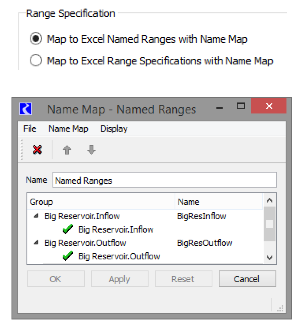
Map to Excel Named Ranges
Under the Map to Excel Named Ranges with Name Map option, the user would set up named ranges in their Excel workbook. Named ranges are a feature of Excel where a number of cells can be selected and assigned a name by the user to identify these cells. The Name Map created in RiverWare and selected in the General tab of the dataset dialog then will associate the RiverWare slot with the named range as seen in the following example name map. In this case, BigResInflow and BigResOutflow are named ranges in the Excel sheet.
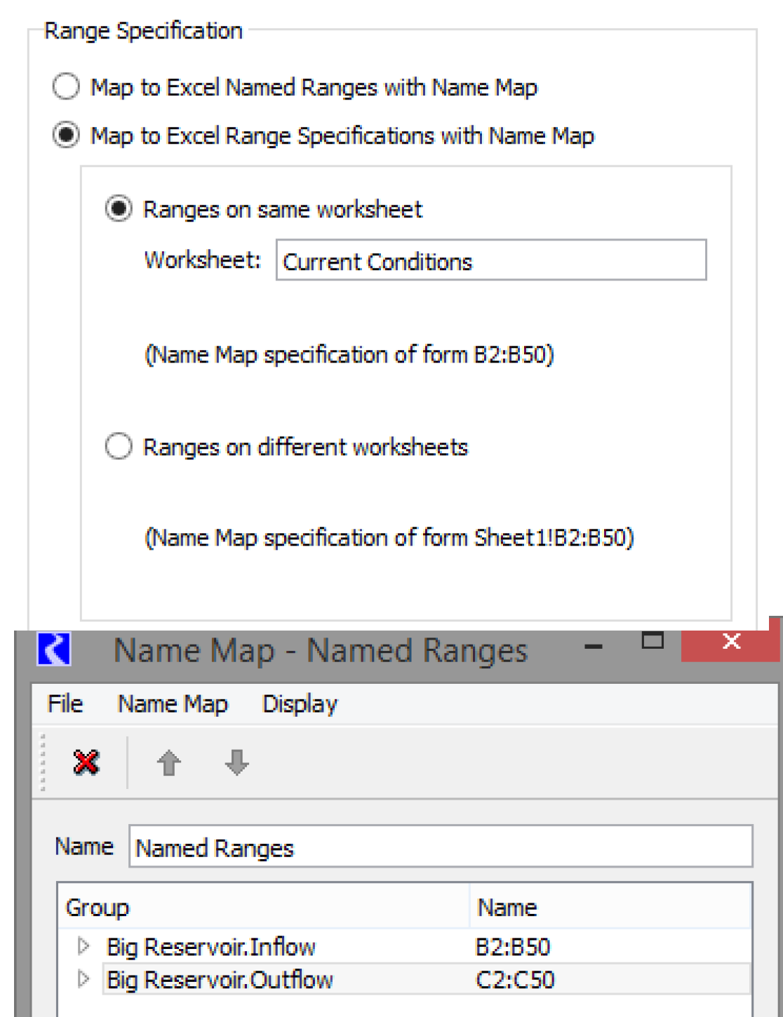
Map to Excel Range Specifications
In the Map to Excel Range Specifications with Name Map option, there are two ways to specify ranges for slots. If all the ranges for the slots are on the same worksheet, then the Ranges on same worksheet option can be used. Here the worksheet name is specified in the Worksheet text box. Ranges specified in the name map can be of the form B2:B50, meaning the range will be from cell B2 to cell B50 of the specified worksheet. Figure 4.20 shows an example of the type of Name Map created and selected on the General tab of the dataset dialog for this approach.
Figure 4.20
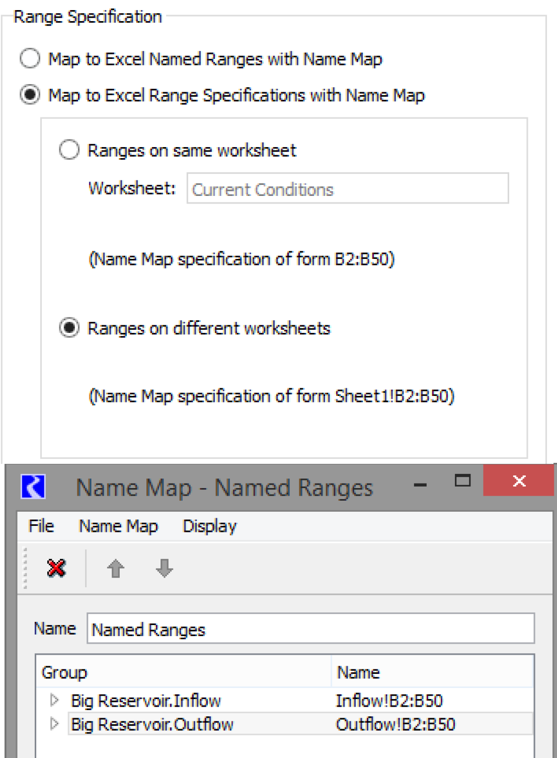
If ranges for the slots are on different worksheets then the Ranges on different worksheets option must be used. Under this option, ranges specified in the name map must include the worksheet name as part of the range specification in the form Sheet1!B2:B50. In this way, ranges referring to different worksheets can be included in the same name map. Figure 4.21 shows an example of this type of Name Map.
Figure 4.21
Specify Range Offset
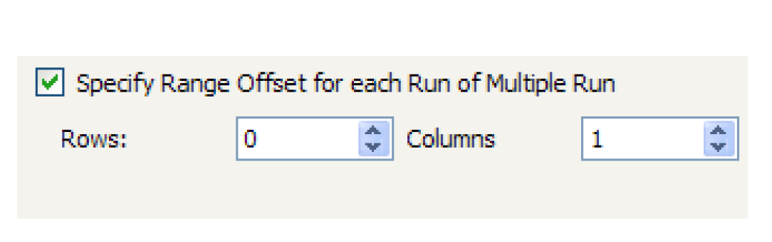
Under all variations of the Map by Spreadsheet Ranges approach, there is an option available to Specify Range Offset for each Run of Multiple Run. In a multiple run, the user may want to read different data into a slot for each run or write out the results for the slot under each run. If the option is checked, the mapped range for the slot is used for the first run, and the specified row and column offset is applied for each run thereafter. For example, the range for a slot specified in the dataset’s name map could be Sheet1!B2:B50 and the offset specified here could be 0 rows and 1 column. For an input DMI in a multiple run, the first run will read range B2:B50 on Sheet1 into the slot, the second run will offset one column and read range C2:C50 on Sheet1, the third range D2:D50, etc. For an output DMI, the slot’s results from the first run will be written to range B2:B50 on Sheet1, results from the second run will offset one column and be written to range C2:C50 on Sheet1, the third to range D2:D50, etc.
Slot Mapping—Header Text and Sheet Names Approach
The Map by Header Text and Sheet Name approach is the alternative to using ranges to move RiverWare slot data to or from Excel. The approach uses a row header, a column header, and a worksheet name to map Excel data with a RiverWare slot. Figure 4.22 shows an example of the dataset dialog with this configuration selected.
Tip: When setting up an input DMI using this Excel dataset approach (especially the first time), it is often easiest to configure the DMI as an Output DMI first, run the DMI to create an Excel spreadsheet with the right formatting and desired structure. Edit that spreadsheet or use it as a guide for setting up your data in that format. Then, configure the DMI to be an Input DMI that will bring your data into RiverWare.
Using Name Maps
Name maps are not needed in the header approach. However they can be used to map to a different name in Excel. The following is performed for each slot:
• If there is no name map, the RiverWare object and slot name is used in Excel.
• If there is a slot mapping only, the specified mapped name is used in Excel.
• If there is an object mapping only, the mapped object is used for the object name followed by a period and the RiverWare slot name. This combined string is used in Excel.
• If there is a slot and object mapping, the mapped object name is used followed by a period and then the mapped slot name. This combined string is used in Excel.
Slot Types
An Excel dataset using the header approach can either import/export Series Slot data or Table / Periodic / Scalar Slot data, but not both. Choose the desired slots that will be accessed by this dataset.
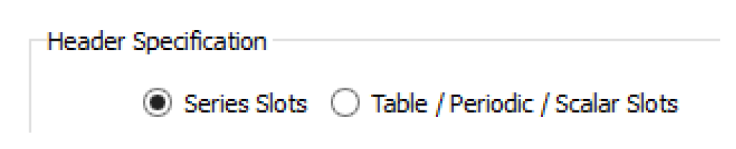
Figure 4.22
Series Slots Configuration Options
When the Series Slots option is chosen, you can specify the format of the series slots in the spreadsheet.
The Header Orientation frame provides four orientation choices for how timesteps, slots, and runs will map to rows, columns, and sheets in Excel. For example, the first orientation as selected in the adjacent screenshot indicates that rows are timesteps, columns are slots, and worksheets are runs.
Note: Orientations for putting each timestep on a separate sheet are not supported.
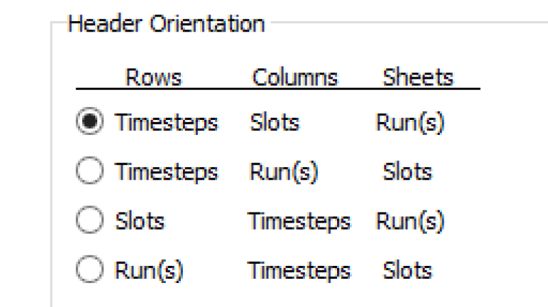
Figure 4.23 shows an Excel spreadsheet with the first orientation. In this orientation, timesteps are rows, so the timestep header is the first column with a time label for each row. Similarly, the slot header is the first row with each column labeled with the slot name. Sheets are runs, so the sheet is named with the single run name specified in the dialog.With the orientation specified, the data in Excel associated with a slot over a time range can be found for reading via an input DMI, or can be found and overwritten, if existing, or be newly created by writing via an output DMI.
Figure 4.23
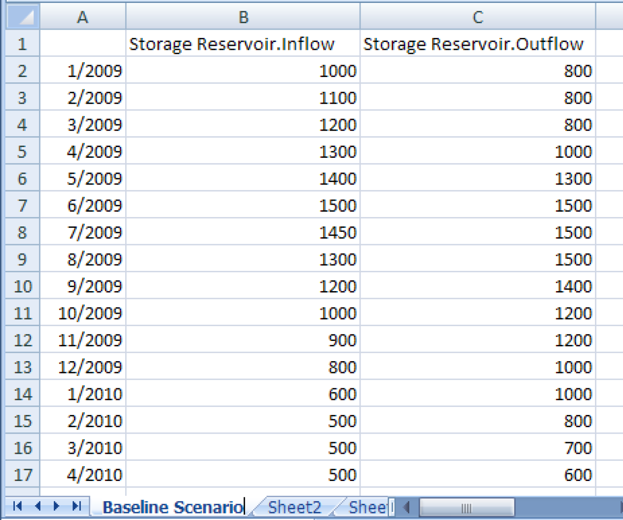
Note: On subsequent executions of an output DMI using the header approach, if there is already a matching header, data will be overwritten. If there is not already a matching header, the new header and data will be appended to any existing data. So in the example spreadsheet above, if you change the output slot from StorageResevoir.Outflow to Storage Reservoir.Storage and rerun the DMI (without deleting the.xlsx file), it will replace the inflow column with any new data and will append a StorageReservoir.Storage column after the Outflow column (i.e. it won’t replace the outflow column with storage, but will instead append it).
The headers may not always be the first row and the first column. To accommodate these cases, an option is provided to specify how the headers are offset from the corner of the spreadsheet. By indicating how many rows and how many columns the header is offset from the upper left corner of the spreadsheet, the user can match how data resides in an existing spreadsheet or indicate where the headers and data should be written to a new sheet.
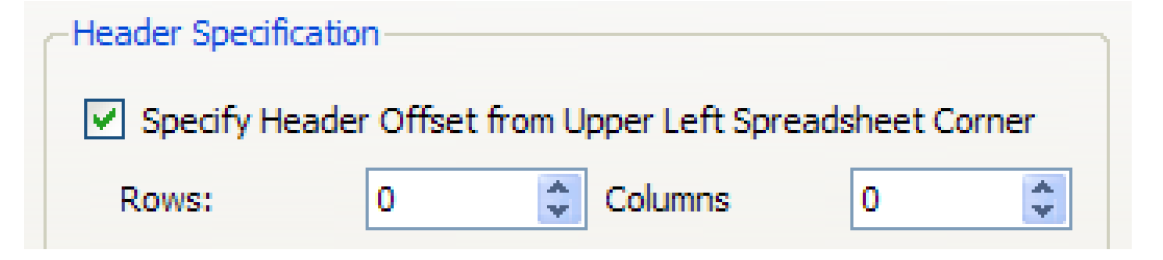
Table / Periodic / Scalar Slots Configuration Options
When the Table / Periodic / Scalar Slots option is chosen, you are not allowed to specify the format of the slots in the spreadsheet. Instead, there is a very specific format that is used. Figure 4.24 shows a sample workbook. Table slots have a header merged cell for the slot name, cells for column headers, and the columns that contain row headers and data columns. Periodic slots include a column of dates, one or more columns of data, and a header cell. Scalar slots are represented by a header cell and a value cell.
Note: The associated slots in RiverWare are also shown. The sheet name is Run0 because that option (described below) is used.
Figure 4.24
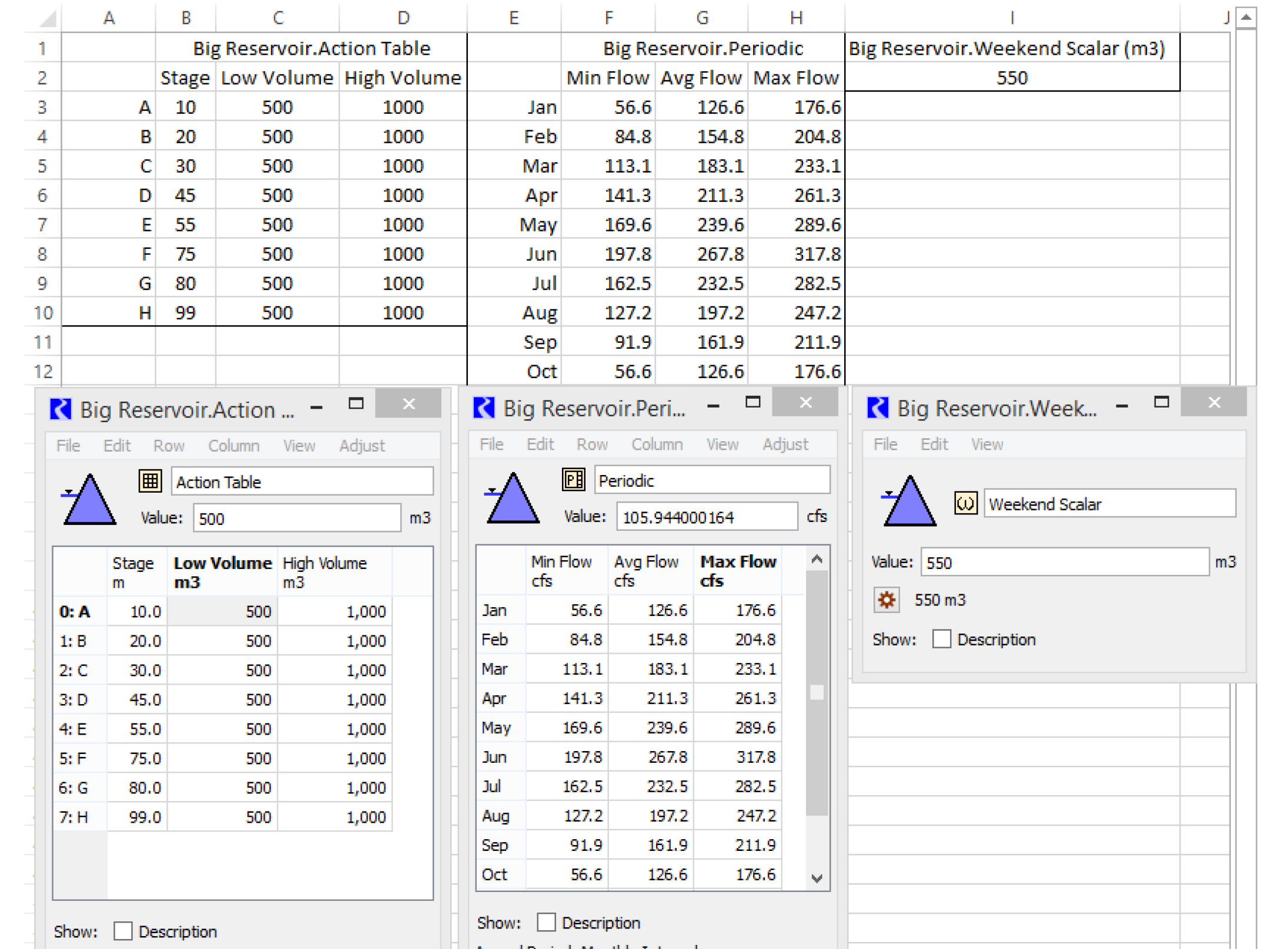
Table / Periodic / Scalar Slot DMI Limitations
Functionality to import/export Table, Periodic, and Scalar slots from/to Excel has the following limitations:
• Multiple runs are supported by having sheets with either the RunN or TraceN format.
• Using an offset from the first row/column is not possible.
• The Use Unit Name with Slot Name is only supported for Scalar slots. Units in Table or Periodic columns are not supported.
• Column and row labels must be specified in Excel as strings, even when the labels are the string representation of numbers (which is common for row labels). Unfortunately, Excel tries to convert string numbers into Numbers. To prevent this, quote numeric column and row labels with a leading apostrophe, for example '10.
• Table or Periodic slots with the DATETIME unit type are not supported.
• Importing a Table slot from Excel can only resize the number of rows in RiverWare. The number of columns cannot be changed.
• Importing a Periodic slot from Excel must match exactly the number of rows and columns. Changing the number of column or rows is not allowed.
• Periodic slots export includes row labels (i.e. dates) in the Excel sheet. But on import, the dates must match the row labels or an error will occur. It is not possible to change the periodic dates, interval or period based on data in Excel. These must all be configured in the slot before importing values from Excel.
Run Name Type
The Run Name Type options indicate how runs in the Excel workbook will be labeled.
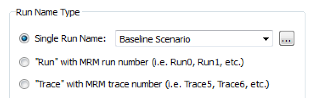
Use one of the following options:
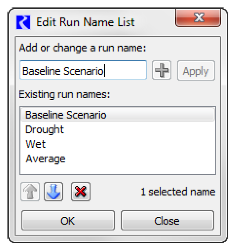
• Single Run Name. For a single run, the Single Run Name must be entered, which will be used to map to the appropriate dimension in Excel depending on the orientation selected (either row, column, or sheet). Either type the text directly into the field or use the chooser to select from a list of possible values. Use the button to edit the list of possible values. In the Edit Run Name List dialog, add, change, or delete possible Run Names using the buttons. A Run Name List can be copied from one Excel Dataset to another using copy/paste operations in the right-click context menu.
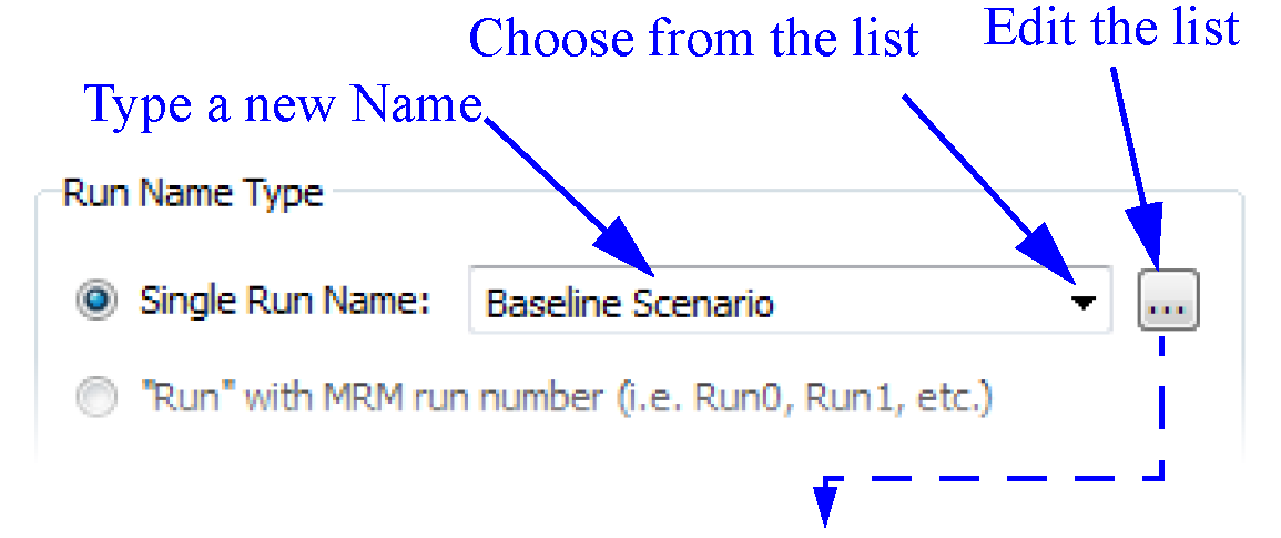
• “Run” with MRM run number. For multiple runs, a single run name is not adequate to label each run individually. Two options are provided for labeling multiple runs. If “Run” with MRM run number (i.e. Run0, Run1, etc.) is selected, then the run name used for mapping to Excel will be the word Run followed by the index number of the run within the multiple run.
Note: The index number used is zero-based to be compatible with how multiple run data has historically been written out of the ExcelWriter tool. The Run option cannot be used in the case of a distributed MRM run because run numbers start at zero in each distributed piece. A DMI error message is issued in this situation.
• “Trace” with MRM trace number. If “Trace” with MRM trace number (i.e. Trace5, Trace6, etc.) is selected, then the run name used for mapping to Excel will be the word Trace followed by the trace number of the run within the multiple run. Trace numbers are a one-based index into the runs, but the initial trace number for starting the multiple run can be specified by the user. Trace numbers can be used successfully with distributed MRM runs. See “Input DMI Runs” in Solution Approaches for details on setting up trace numbers in MRM.
Note: Excel worksheet names (i.e. the worksheet tab label) must be less than or equal to 31 characters; this limit is imposed by Excel. If you choose to have Runs on sheets and you type in text in the Single Run Name field, it is limited to 31 characters. If you choose to have Slots as sheets and your slot name is more than 31 characters, when the DMI is run the slot is not written/read and a message is posted. In this case, use Name Maps to map the slot names to shorter names that will be accepted by Excel.
For Series Slots approach, an option is provided to Use Begin Timestep Time Instead of End of Timestep.
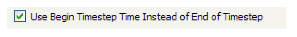
Timesteps in RiverWare are dated with the end of timestep time, that is, a 1 Day timestep for the last day of the year 2000 is dated 12/31/2000 24:00. If the begin timestep option is not checked, this date is written to (and is expected to be read from) Excel as 12/31/2000 23:59. A minute is subtracted compared to the RiverWare end of time so that the date appears in the correct month and year in Excel. (Excel has no concept of a 24:00 display, so 12/31/2000 24:00 is interpreted by Excel as 1/1/2001 00:00, which would appear to be the wrong month and year.)
If Use Begin Timestep Time Instead of End of Timestep is checked, then the timestep is written to (and is expected to be read from) Excel as the beginning of timestep in RiverWare. For the above example, the time in Excel would be 12/31/2000 00:00. This option may be particularly useful if the user is entering data into Excel and is typing in 1 Day timesteps as 12/30/2000, 12/31/2000, 1/1/2001, etc., which end up by default with 00:00 hours and minutes in the Excel date format. With the begin timestep option checked, the data associated with these times will be moved into RiverWare for their correct timesteps.
An option is also provided with the header approach to Use Unit Name with Slot Name. In an output DMI, this option will attach the unit name to the slot name when the slot name is written out to its appropriate row, column, or sheet, depending on the orientation selected. The format is the slot name, a space, and the unit name in parentheses, such as Storage Reservoir.Inflow (cfs). In an input DMI, this option means that the DMI will expect the unit name to be attached to the slot name as indicated above when it is looking for the slot in the Excel headers or sheets.
Connection Process
The final part of the Excel DMI tab is the choice of Connection Process as shown in Figure 4.25.
Figure 4.25 Screenshot of the Excel Dataset Connection Process configuration
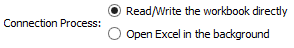
This configurations setting specified how the RiverWare DMI should connect or communicate with the Excel workbook. The two choices are:
• Read/Write the workbook directly: (Default) Read or write the data directly to the Excel workbook file, without opening the Excel application. This option typically has faster performance because Excel is not opened in the background. But, without opening Excel, there is no way to evaluate formulas in Excel or execute other automatic workbook operations.
• Open Excel in the background: Open Excel in the background, possibly to evaluate formulas, and then read or write the data. This was the original and only approach through RiverWare version 7.4. In this approach, the Excel application is opened in the background and then the DMI interacts with Excel through the Component Object Model (COM) interface. This approach requires that Excel is installed on the computer.
Name Mapping
It is likely that RiverWare object or slot names do not match their associated database names. For example, the reservoir inflow is called Inflow in RiverWare while in DSS Part C, it is instead called RES-INFLOW. Because different databases use different naming conventions, there is no way for RiverWare to know the database’s naming convention. The name mapping tool provides a tool for the user to specify the link between the two naming systems. The name mapping tool allows the user to define multiple name mappings.
Note: If the names are mapped within the database itself, as they are in HDB, a Name Map is not needed.
Note: For DSS datasets, there is no need to create a name map if the map is strictly to specify a different case. This is taken care of automatically. For example, a name map is not necessary for a reservoir in RiverWare called BigLake while in the DSS database, it is called BIGLAKE.
Configuring Name Mapping
To bring up the name mapping editor from the DMI Manager, the user selects Utilities, then Name Maps.
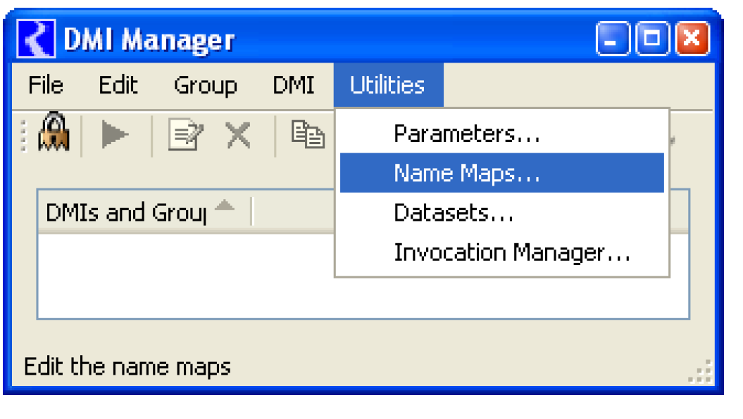
This opens the Name Map Manager dialog. Selecting the  icon adds a new Name Map to the editor and gives it a default name.
icon adds a new Name Map to the editor and gives it a default name. 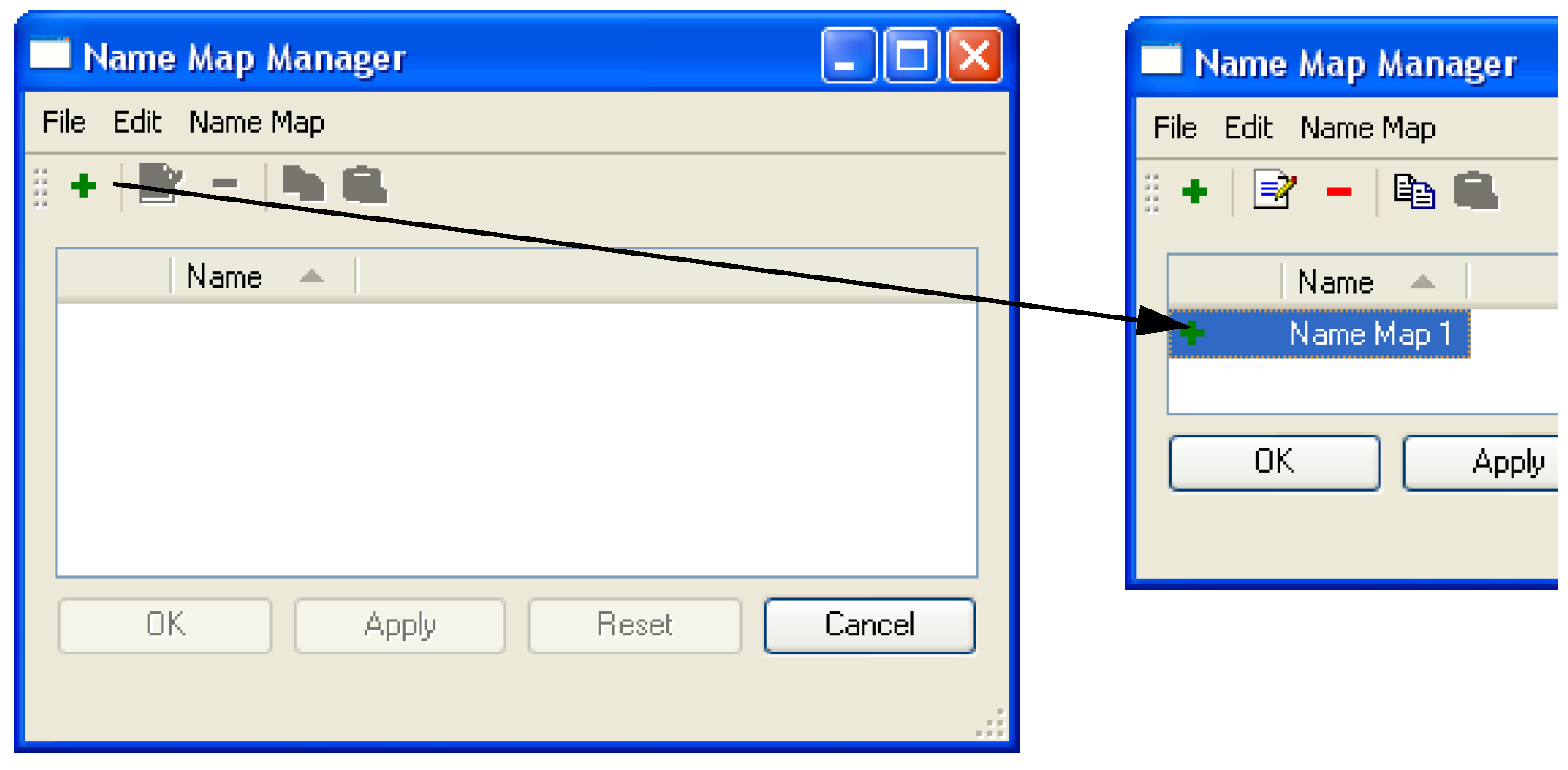
Double-clicking the newly added Name Map opens the Name Map dialog as shown in the following screenshot. In this dialog, the user is able to edit the name of the Name Map. Selecting Name Map, then New adds a new entry to the list.
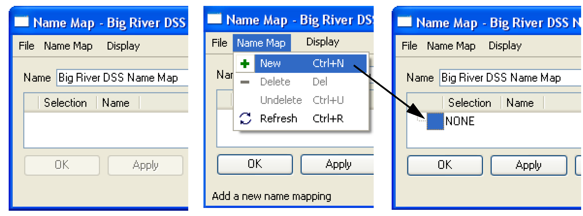
Selecting the newly selected entry opens the context menu options shown in Figure 4.26. Either select Select Simulation Object or Select Slot. This action opens the selector dialog for the appropriate selection. In this dialog, the user selects the desired objects or slots that will be part of this Name Map. If accounting is enabled, supplies, accounts, exchanges, and paybacks are also available. Use the filters and wildcards to select generic slots. For example, the user could select Reservoir.Inflow as an entry. See “Creating a Name Map of All Reservoir.Inflow Slots” in User Interface for details on using the selector. The selections made here are considered dynamic root selections. That is, the selection is saved with the model file and is automatically updated if objects or slots are added to or removed from the model. This is especially useful when using wildcards.
To define the data name, in the Name Map manager, select the blank area to the right of the entry under the word Name. This is where the user specifies the database’s variable name for the entry. Figure 4.26 shows an example.
Figure 4.26
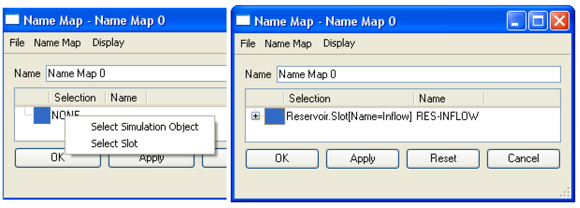
Name Map Ordering and Priorities
The entries in the Name Map are prioritized with the highest priority first. If there is a conflict between two entries, the entry with the highest priority takes precedence and the other entry becomes disabled with a red X. This means that if there is a red X, there is a higher priority selection that controls the item. For example, in Figure 4.27, the first entry for ResA.Inflow (INFLOW) takes priority over the second entry (RESINFLOW). The green check marks show that the first item is controlling the selection. This functionality allows users the functionality to create a name map in a generic case but redefine it in special case.
Figure 4.27
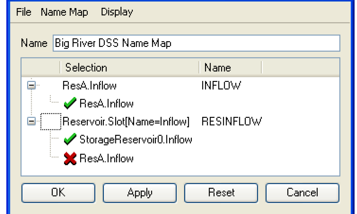
Because entries in the Name Map are prioritized, by default, they are ordered by this priority. The user is able to change the entries by using the Display menu and selecting Custom. Once in custom mode, the user select an entry (Selection and Name row) and then use the up and down arrows  or Display, then Move Up or Display, then Move Down file choices to rearrange rows. To return to prioritized mode, the user selects Display, then Priority. Regardless of the ordering, the name maps are stored according to priority; custom order is just for display.
or Display, then Move Up or Display, then Move Down file choices to rearrange rows. To return to prioritized mode, the user selects Display, then Priority. Regardless of the ordering, the name maps are stored according to priority; custom order is just for display.Sharing Database DMIs
The Database DMI utility includes a feature that allows the user to Export and Import the Database DMI configurations. The user is able to export and import Database DMIs, Datasets, and Name Maps. Following are instructions and descriptions of both exporting and importing Database DMI configurations.
Export
To export the Database DMI configuration, the user selects File, then Export Database DMI from the DMI Manager. The Database DMI Export dialog appears.
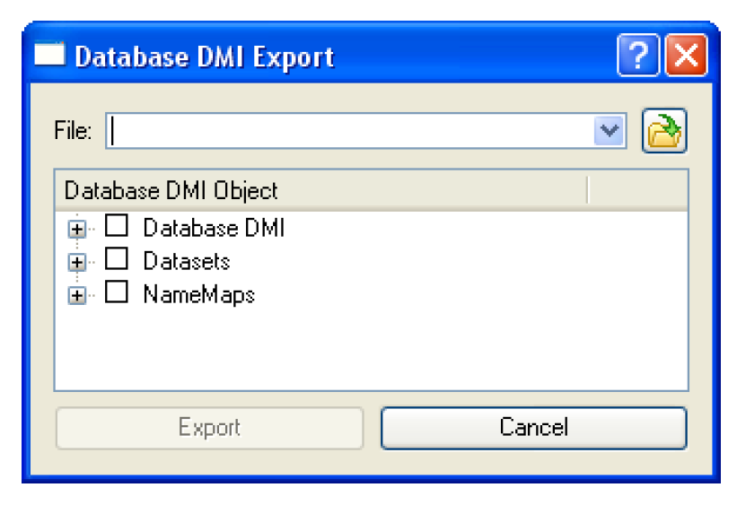
The user types a file path into the File field or selects an existing file using the browser button.
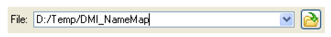
The user selects the  symbol to expand the tree view. Selecting the check boxes selects the Database DMI, Dataset or NameMap to export. Selecting the top tree level multiple times cycles through selecting all of the items, selecting none of the item, and the last selection made. Right-clicking on a Database DMI or a Dataset name, a context menu allows the user to Select the Database DMI and Its Dependencies as shown in Figure 4.28.This allows the user to select not only the Database DMI, but also the Dataset and/or NameMap associated with the selection.
symbol to expand the tree view. Selecting the check boxes selects the Database DMI, Dataset or NameMap to export. Selecting the top tree level multiple times cycles through selecting all of the items, selecting none of the item, and the last selection made. Right-clicking on a Database DMI or a Dataset name, a context menu allows the user to Select the Database DMI and Its Dependencies as shown in Figure 4.28.This allows the user to select not only the Database DMI, but also the Dataset and/or NameMap associated with the selection.Figure 4.28
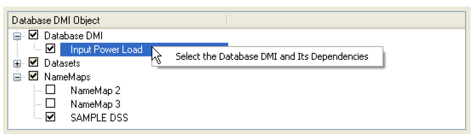
Once a file is entered and a selection is made, the Export button becomes active. Selecting Export will export the configuration to the file.
Import
Importing a set of configurations is similar to exporting. The user selects the File, then Import Database DMI menu on the DMI Editor to open the Database DMI Import dialog.
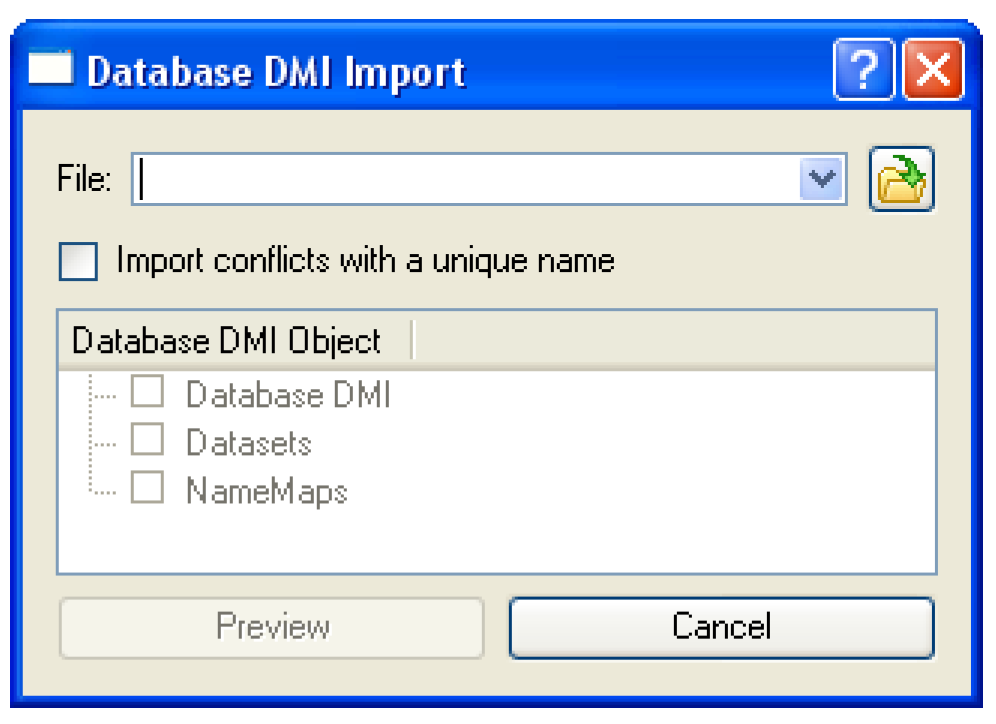
The user types in the file name or uses the browser to select the file to import. Selecting the Preview button reads the file and displays the items in the file. Selecting the  symbol expands the tree view.
symbol expands the tree view. 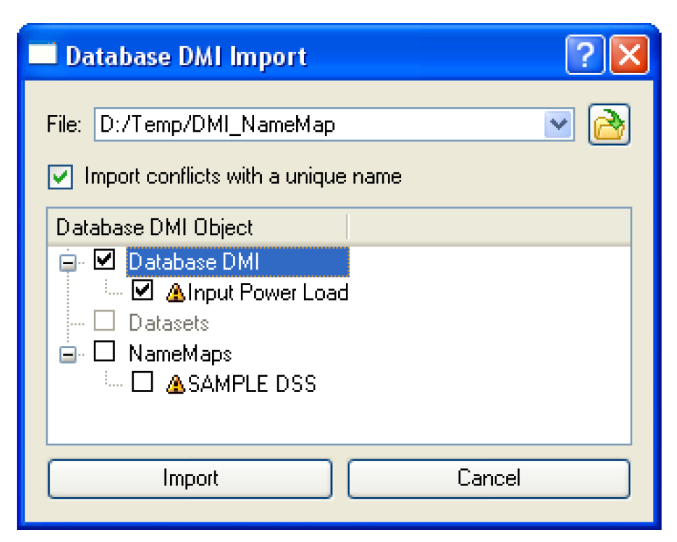
The user then selects the items to import. If the item already exists in the model, a small warning sign is displayed. Toggle on the Import conflicts with a unique name button to import the item and give it a new name. In addition, when this option is checked the imported Database DMIs will be modified access any newly imported Datasets and Name Maps that are also imported.
If the checkbox is cleared and there is a conflict, the import will overwrite any existing items of the same name in the model. When the user is satisfied with the selection, selecting Import brings the items into the model.
Revised: 11/11/2019