
Low-flow Releases
The Low-flow Release policy computes the reservoir outflows to meet a low-flow demand at a downstream control point. If a control point’s demand can be met by multiple reservoirs, the fullest reservoir is considered first and releases as much as possible, then the next reservoir is considered. To set up this operation, the user must select methods and implement rules that call the predefined MeetLowFlowRequirements function.
Model Setup
The user must select methods on each control point and reservoir involved in the low-flow operation. Also, a computational subbasin must be created and methods must be selected on that subbasin.
Control Point Methods
For a control point with a low-flow requirement, the user should select a method in the Low-flow Requirement category to specify how the demand is represented. The valid options are as follows:
• Low Flow Periodic Lookup. The demand is specified in a periodic slot; see Low Flow Periodic Lookup in Objects and Methods for details.
• Reservoir Level Lookup. The demand is specified in a periodic slot that relates a reservoir level to the demand; see Reservoir Level Lookup in Objects and Methods for details. If the specified reservoir is disabled and is set to Pass Inflows, no low-flow requirement can be computed; see Low-flow Requirements Based on Disabled Reservoirs for details.
Both of these methods add the slot Low-flow Reservoirs, which is used to specify the upstream reservoirs that can serve the low-flow demand.
Reservoir Methods
On each reservoir that can possibly serve a Low-flow demand on a control point, the user should select the Enable Low-flow Releases method in the Low-flow Releases category; see Enable Low Flow Releases in Objects and Methods for details. This method adds the Low-flow Release slot to hold the result of the policy and the Maximum Low-flow Delivery Rate which is the maximum flow that can be released from the reservoir to meet low-flow demands.
Computational Subbasin Methods
A computational subbasin should be created that contains the objects involved in the low-flow release. Typically, the same subbasin used for the Flood Control rule can be used. On this subbasin, the user should select the Operating Level-Based method in the Low-flow Releases category; see Operating Level-Based in Objects and Methods for details.
RPL Implementation
A rule will need to be created for each control point that has a low-flow requirement. In the rule, a predefined RPL function, MeetLowFlowRequirement, is used to compute the required low-flow releases for each reservoir. The function will take a computational subbasin and a control point as an argument. See MeetLowFlowRequirement in RiverWare Policy Language (RPL) for details.
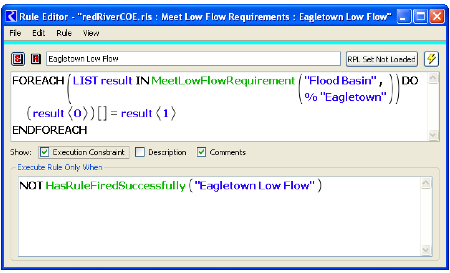
Figure 3.6 shows a sample rule that meets the Eagletown low-flow requirement using the computational subbasin name FloodBasin. The execution constraint forces the rule to execute only once.
Figure 3.6 Sample low-flow release rule
MeetLowFlowRequirements Function
See MeetLowFlowRequirement in RiverWare Policy Language (RPL) for details on this predefined function.
The function iterates through each of the Low-flow Reservoirs specified on the control point. For each control point (i.e. each time the RPL function is called), the following steps will take place:
1. The Low-flow Deficiency slot is checked to see if there is a low-flow shortage. If not, the Low-flow Release is zero for each reservoir. The Outflow Should not be reset if the Low-flow Release is zero.
2. If there is a deficiency, the following steps are taken:
a. The reservoirs in the Low-flow Reservoirs slot are sorted by level in descending order. Reservoirs below the bottom of the conservation pool are excluded.
b. Each reservoir (beginning with the most full reservoir) makes a release until the requirement (in the Computed Low-flow Requirement slot) is met, the Maximum Low-flow Delivery Rate (on the reservoir) is met, or the reservoir reaches the bottom of the conservation pool (whichever value is lowest). Routing coefficients (travel times) are not considered.
c. The RPL function returns a list of paired items, the Low-flow Release slot and the value to be set on the slot (for each reservoir). The rule makes the assignment to the Low-flow Release slot. The new Outflow and Outflow slot is also returned by the rule function. A ForEach statement is used to make the assignments.
When the reservoir Outflows are set, the system will solve to route the flows downstream. The Low-flow Deficiencies will be recomputed to reflect the low-flow releases. The reservoir Operating Levels will be recomputed to reflect the new releases. Then the next rule will execute to determine the low-flow releases for the next control point.
Setup to Avoid Routing Low-flow Releases
In the MeetLowFlowRequirement function, routing is not considered, but in the subsequent simulation of the releases, routing is considered. As a result, the released flow often does not meet the demand. This section describes the issues with the approach, then presents a structure to avoid routing of the low-flow releases.
Releases are made from reservoirs to meet minimum flow criteria specified at downstream Control Points. In SUPER, routing is considered in the low-flow release calculation as follows: Today's low-flow release fills deficiencies noted in yesterday's final results. Yesterday's final results are adjusted by today's low-flow release. In the RiverWare MeetLowFlowRequirement function, the current timestep’s low-flow release deficiency is used as the low-flow demand and water is released from the reservoir to meet this demand, but routing is ignored. Example 3.2 illustrates.
Example 3.2
Assume a control point that is 1 day travel time downstream of the reservoir with a 1000 cfs low-flow requirement every day. Assume there are no other releases, no surcharge or flood control, and hydropower is inactive. On the current day, let's say there is 500 cfs at the control point from uncontrolled area flows. The reservoir would make a 500 cfs low-flow release to make up for that deficiency. However, that release would not get there until the next day. On the next day, there are no other releases or inflows. So the low-flow deficiency is still 500 cfs (the requirement is 1000 cfs and there are 500 cfs at the control point from the previous day). The reservoir would again make a 500 cfs release to cover the deficiency. However, that wouldn't get there until the next day. On the next day there is still a 500 cfs deficiency (let's keep assuming there are no other releases and no uncontrolled area inflows). So the reservoir would again make a 500 cfs release.
This example illustrates the problem with the existing RiverWare approach: the minimum flows may never be satisfied. RiverWare tries to make up the current timestep’s deficit, which often does not arrive at the control point until future timesteps. This leads to less water being released. In general, the releases for this purpose are smaller in RiverWare than in SUPER.
The model can be modified to address low-flow issues in a manner consistent with SUPER low-flow handling. That is, reservoir releases made specifically for low-flow requirements at a downstream control point are passed through secondary flow paths avoiding routing between the reservoir and control point. Below is the approach.
Creation of Secondary Flow Paths
To avoid routing the effects of low-flow releases, designated low flows were passed around routing reaches by creating a secondary flow path between a control point and its associated upstream reservoirs as follows:
1. a non-routing reach was created for use in diverting the designated low flows from the primary (existing) flow path.
2. a water user was created to the side of the primary flow path, facilitating diversion of water from the non-routing reach and returning flows to the routing reach’s Return Flow slot.
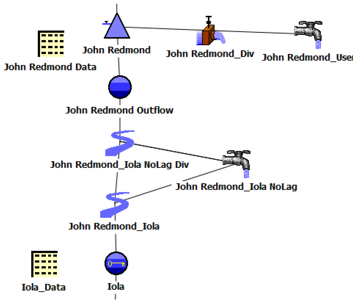
Figure 3.7 shows this setup. The secondary flow path was created by linking these two objects. The non-routing reach Available For Diversion slot was linked to the water user Incoming Available Water slot. The non-routing reach Diversion slot was linked to the water user Diversion slot. The water user Return Flow slot was then linked to the routing reach’s Return Flow slot which flows into the routing reach after the main channel flow has been routed.
Figure 3.7 Sample setup to avoid routing low-flow releases
The non-routing reach was then inserted into the existing flow path, with existing links being restructured to provide inflow / outflow connectivity. The outflow / inflow link connecting the routing reach object and its upstream object(s) was deleted. Outflow from the upstream object(s) instead was linked to the inflow of the new non-routing reach. Outflow from the new non-routing reach was linked to the inflow of the routing reach.
In the case where a reservoir provides low-flow releases to two (or more) downstream control points, this structure must be created around each routing reach between the reservoir and the lowest control point. Flows destined for low-flow demand at the lowest control point should pass through secondary flow paths created for flows destined for control points higher up in the river system. It is not necessary to create more than one secondary flow path around a single routing reach, the rules will determine the quantity of water to divert through the secondary path. For this setup (in the initial implementation), each reservoir should have a companion data object. On the data object, you should add slots to hold the low-flow releases for each downstream control point: Reservoir Data.LowFlow for CP. For example, there may be a slot “John Redmond Data.Low-flow Release For Iola”
Method Selection on Objects
On each of the new water user objects, the Return Flow category was set to Fraction Return Flow, and then the Fraction Return Flow Input category was set to Periodic Fraction. A value of 1.0 was entered into the Periodic Fraction periodic table. This sets up zero consumption in the water user; all diversion becomes return flow.
On each new non-routing reach object (named with *NoLag Div in the sample model), the Routing method was set to No Routing. Also, on each of the new water users (named with *NoLag in the sample model) the Periodic Diversion Request method was selected from the Diversion and Depletion Request category. A value of 0.0 was input into the only cell in the Periodic Diversion Request slot. This method executes at the beginning of the run and on each timestep looks up a value in the Periodic Diversion Request slot. The computed value is set in the Diversion Requested and Depletion Requested slots. This serves to initialize the water users so their diversion request is zero at the beginning of the run.
Local Inflow and Solution Direction was set to No Local Inflow, Solve Outflow on each of the new non-routing reaches. This was discovered as necessary due to rule execution and convergence errors during simulation resulting from an unintended solution direction caused by the lagging reaches.
Rules to Divert to No Lag Secondary Flow Paths
When using this setup, a slightly different structure should be used for performance and readability. For each control point where the flows should not be routed, there should be two rules:
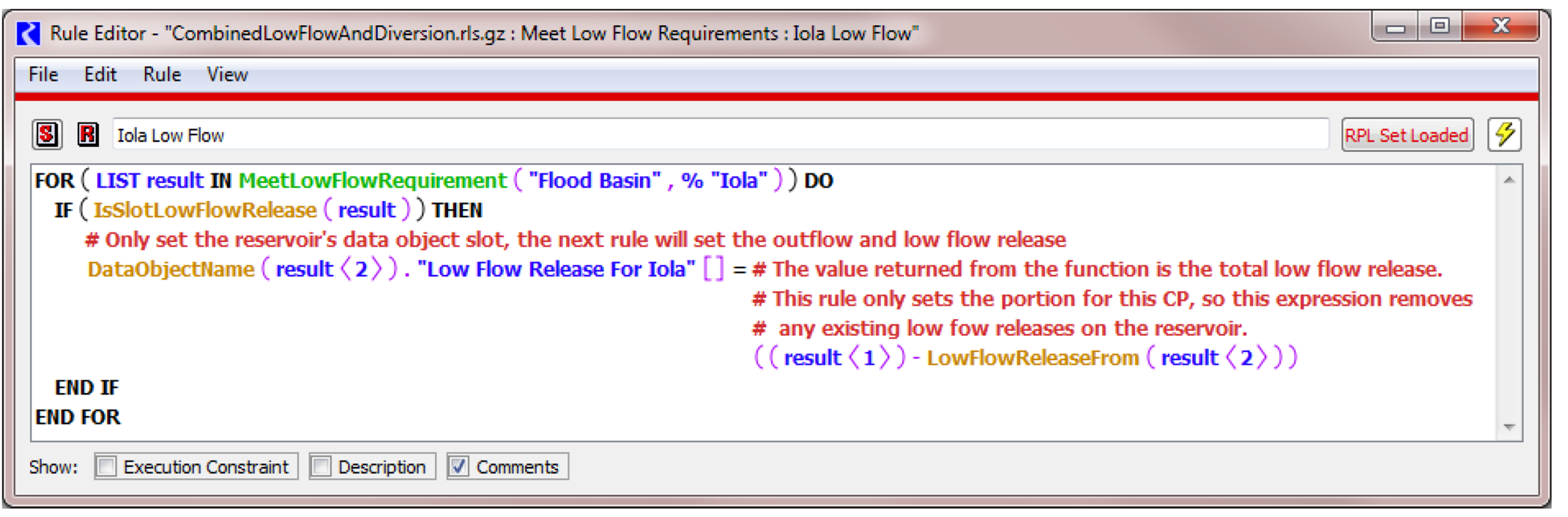
• A lower priority rule computes the necessary low-flow release for the specified control point, but sets the value on the Reservoir's data object slot. No dispatching happens after this rule. Figure 3.8 shows an example.
Figure 3.8 Sample rule to compute low flows needed and set it on a data object
• The higher priority rule that applies it to the reservoir by increasing the Outflow and Low-flow Release slot. It also increases the NoLag.Diversion Requested slot. The system will dispatch and solve after this rule finishes. Figure 3.9 shows an example.
Figure 3.9
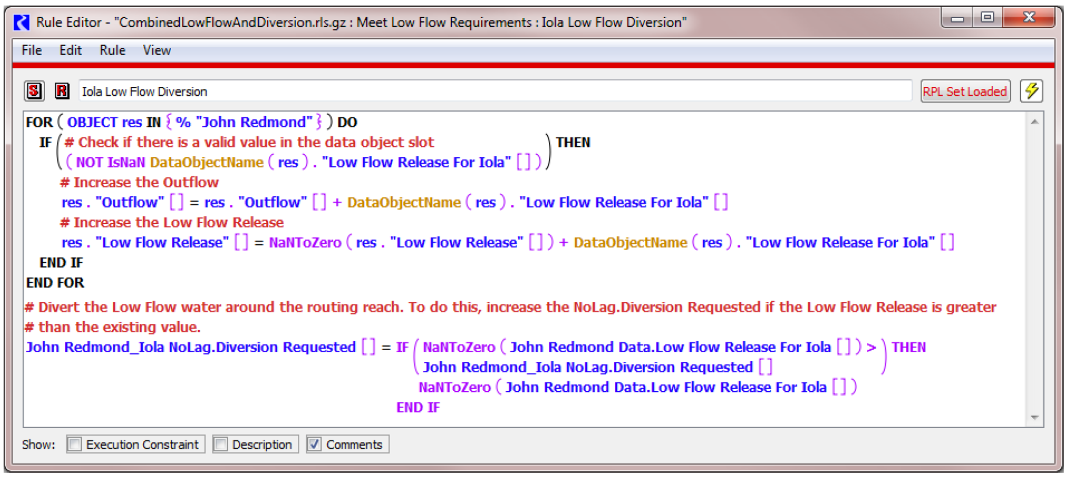
This two rule structure is necessary for performance and readability. Computing the values in the first rule but setting th-m on the reservoir in the next rule improves performance by only dispatching the system once. These rules should be set to execute only once through execution constraints.
Note: Take care if there are multiple low-flow demands. The low-flow diversion rule must divert the correct amount.
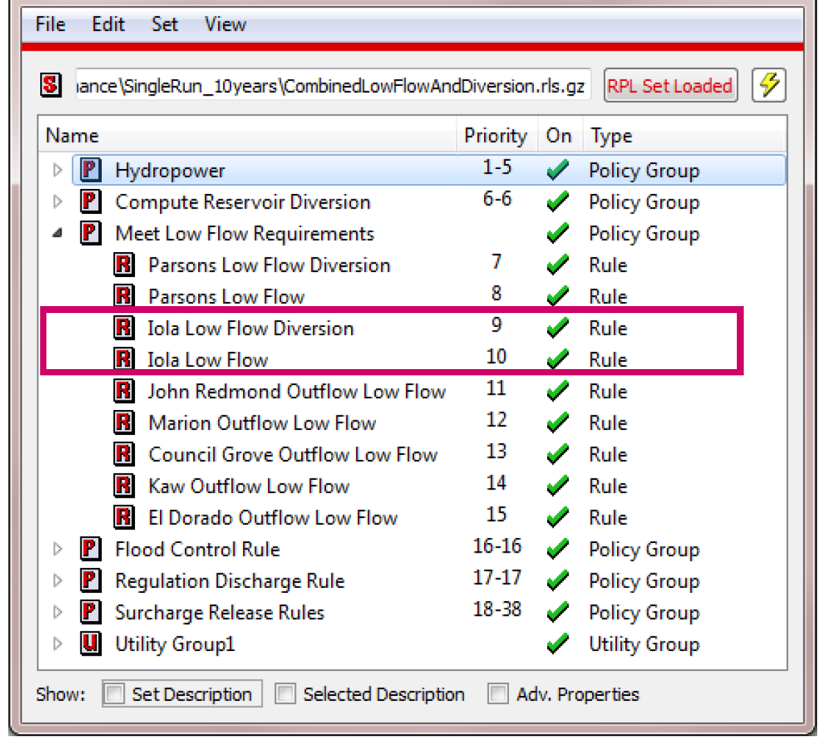
Figure 3.10 Sample ruleset that avoids routing low-flow releases
Revised: 01/11/2023