
Creating a Database DMI
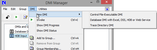
A Database DMI is created from the main DMI Manager dialog using the DMI, then New DMI, then Database DMI with Excel, DSS, HDB or Web Service menu.
There are two ways to define and edit a Database DMI:
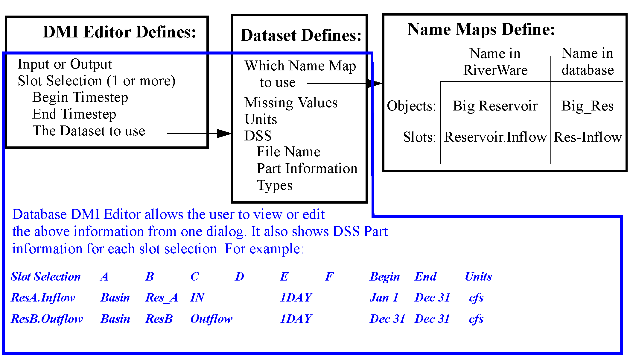
• Define a Name Map, Dataset and then use the Database DMI editor. You create a Name Map, then a Dataset, then a Database DMI that pulls it all together.
• Use the Database DMI Editor. The Database DMI Editor allows you to create a fully functional DSS Database DMI from a single dialog and provides access to other dialogs for Excel, HDB, and web service DMIs. It fully expands the slot selection to show the exact configuration that will be used. For example, it displays that BigReservoir.Inflow will be imported using BigRes Res-Inflow and displays the part information and units that will be used.
Once a new Database DMI is added to the DMI manager, the user can edit it using the Database DMI Editor. The Database DMI Editor dialog provides a convenient place to create, edit, and view database DMIs. It also provides a single dialog for configuration of a fully functional DSS Database DMIs. To that end, it allows the user to specify all required configuration information and as much optional configuration information as is feasible. The real power of this dialog is that the user can see the fully specified information that will be sent to the database, which is especially useful for DSS.
To open the New Database DMI Editor, the user selects Edit, then Edit with New Database DMI Editor. The Database DMI dialog appears.
This dialog is like an editable view into the Dataset Manager. Thus, the user can see what has already been configured in those dialogs but also make edits that will be applied to those pieces. It is important to note that if the user edits a dataset or Database DMI in the editor window, the user cannot also edit the individual components at the same time.
Note: Because there are many approaches to create and edit Database DMIs, there are multiple ways to edit the same information, e.g. you could edit a dataset from both the dataset manager and the Database DMI Editor. To avoid conflicts, the dialog that first starts editing a name map or dataset creates a “lock” on the information and no other dialog can edit that feature. When a lock has been created, the lock icon  is added to any other dialogs that are trying to edit that information. If you see this icon, the information is not editable from that location. Similarly, if a name map or dataset has been scheduled for removal from another dialog, the “delete lock” icon is shown.
  .
.
is added to any other dialogs that are trying to edit that information. If you see this icon, the information is not editable from that location. Similarly, if a name map or dataset has been scheduled for removal from another dialog, the “delete lock” icon is shown. .Figure 4.4 shows a similar figure to Figure 4.2, but with the Database DMI Editor also shown with a DSS dataset example.
Note: The information in each of the components is represented in the dialog, but in a slightly different organization. The parts of the dialog are described in detail in the following section.
Figure 4.4 DMI Pieces of a Database DMI with the parts highlighted that represent the DMI Editor
Conceptually the dialog has four sections from the top to the bottom, as shown in Figure 4.5 and described in the following sections:
• Database DMI Name and Type
• DMI Configuration
• DSS Configuration including DMI User Parameters (Only shown when a DSS dataset is present)
In this dialog, each type of dataset has its own color:
• HDB—orange
• Excel—green
• DSS—pink
• Web service —blue grey
Figure 4.5 Annotated screenshot of a Database DMI
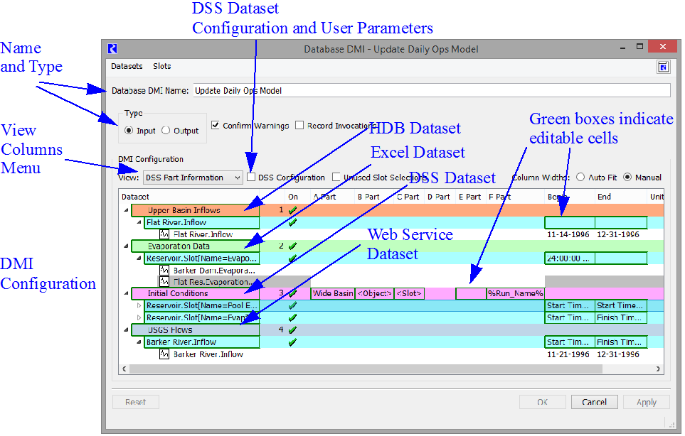
The cyan rows are slot selections. The green boxes are cells in which data entry is possible.
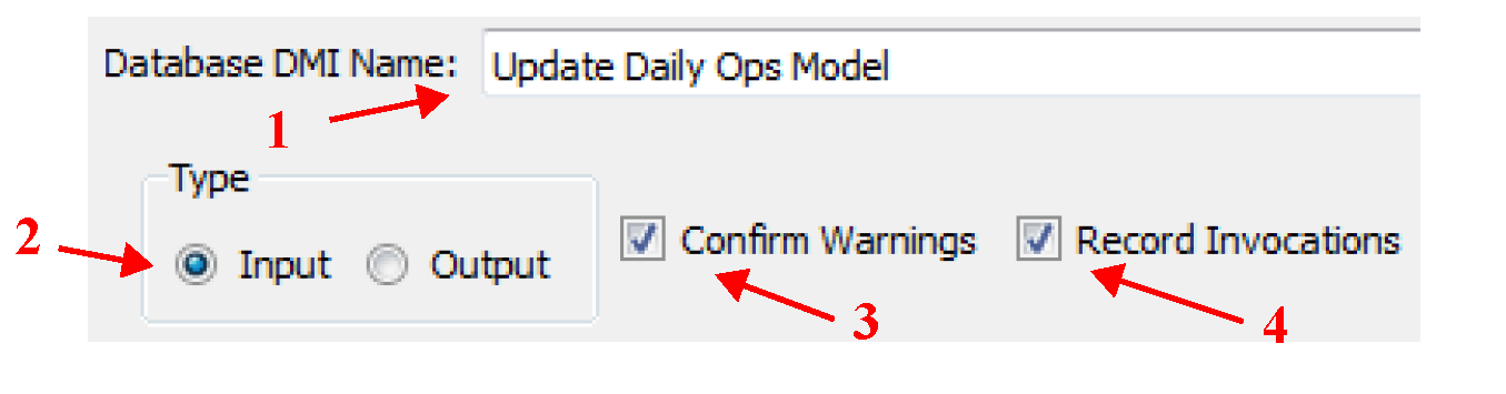
Name and Type
The Database DMI general configuration section (upper section) of the dialog allows you to do the following:
• Specify the Database DMI Name in the text field.
• Specify whether the Database DMI is an Input or Output DMI.
• Specify if you wish to confirm warnings before the Database DMI continues using the toggle.
• Specify whether he DMI manager should record invocations of the DMI. The Record Invocations check box allows RiverWare to maintain information which chronicles input DMI invocations. With this information, values set by DMIs can be cleared on a per-invocation basis. If a user wishes to clear out all values that are input by a DMI, this box should be checked. If a user knows values set by a particular DMI won’t be cleared then it is not necessary to maintain information about the DMI invocations and this box should remain unchecked. (The information occupies memory and could, over time, degrade performance.) The checkbox is only enabled for input DMIs and the default is unchecked. See DMI Invocation Manager Dialog for details on clearing values set by an input DMI.
DMI Configuration
The DMI configuration section (middle section) displays the configuration of the DMI. In this dialog, each type of dataset has its own color:
• HDB—orange 
• Excel—green 
• DSS—pink 
• Web service—blue grey 
The cyan (light blue) rows  are slot selections. The
  are cells in which data entry is possible. This portion of the dialog allows you to:
are slot selections. The are cells in which data entry is possible. This portion of the dialog allows you to:• Create Datasets using the Dataset menu.
• Remove Datasets using right-click context menus.
• Create and define slots selections and time intervals.
• For DMIs with DSS datasets, see and edit the part information for each slot.
• Select the columns to view. See View Columns.
• Show or hide Unused Slot Selections; see Unused Slot Selections.
• Select either Auto Fit or Manual Column Widths.
Note: The first column in Auto Fit mode, only grows to a fixed maximum width.
• In this dialog, tool tips and the status bar (the lower left) are used to show the contents of cells, indicate directions, or additional information.
The information is presented in a tree-view, with each level representing a more detailed specification, as detailed in Table 4.1.
Name | What it is | Tree Level | Items shown |
|---|---|---|---|
Dataset | Entered by user | 1: Highest | Name, type and generic Part information. The Name and Part information is editable. All datasets including HDB, Excel, and web service datasets, are listed. HDB, Excel, and web service datasets can be shown in this dialog but cannot be edited. |
Slot Selection | Slot Selection Name as shown (or modified) in the Selector dialog. It can included wildcards, e.g. StorageReservoir.Outflow | 2: Middle | The begin and end timestep for this selection are shown and can be edited. |
Slots in Selection | Slots that were selected by the Slot Selection shown, including resolution of wildcards | 3: Lowest | Fully specified information as it will be passed to the database. For DSS, this includes Part information, Begin and End Timestep, and units. No editing is allowed |
The following sections describe the editable parts of each of the levels of the treeview.
Dataset
The following actions can be performed for a Slot Selection row:
• Name DSS Datasets. Double-click to edit the name.
• Open HDB, Excel, and web service datasets. Double-click these datasets to edit.
• Disable a Dataset for debugging; see Enabling and Disabling for Debugging.
• Specify the part information. There are many options for specifying the part information. The only restriction is that Part D is not editable and the default for Part E is the timestep size. The part information can be edited by entering text or by selecting text from a right-click context menu. In addition to typing text, you can use the two following items to generalize DSS DMIs:
– Workspace Entities. You can use generic Workspace Entities for wildcarding any part (except Part D which is not editable). Select the desired entity from the right-click context menu. Table 4.2 lists the options.
Workspace Entity | Description |
|---|---|
Slot | The slot name. |
Parent | The item that contains the slot. For a simulation slot, this is the object (e.g. a reservoir). For an accounting slot, this is the account (e.g. a storage account). |
SimObj | The object that contains the item. For both simulation and accounting slots, this is the containing object (e.g. a reservoir) |
Account | The name of the account containing the object. (Valid when accounting is enabled) |
Supply | The name of the supply. For example a supply named, ResAStorageToReachBFish.Supply would result in ResAStorageToReachBFish (Valid when accounting is enabled) |
Exchange | The name of the exchange. (Valid when accounting is enabled) |
Payback | The name of the payback. (Valid when accounting is enabled) |
UpSimObj | Not implemented yet. For a supply, this evaluates to the object that contains the upstream account. |
UpAccount | Not implemented yet. For a supply, this evaluates to the account name of the upstream account. |
DownSimObj | Not implemented yet. For a supply, this evaluates to the object that contains the downstream account. |
DownAccount | Not implemented yet. For a supply, this evaluates to the account name of the downstream account. |
Note: In versions prior to 6.1, Part B was by default the object name and Part C was by default the slot name. Now these need to be explicitly defined for new datasets, existing datasets will be given the <parent> and <slot> entities for parts b and c, respectively.
– User Parameters. You can use parameters in the DSS parts (see DSS DMI User Parameters, for details). To use the parameters in the DSS part information, specify the value with the percent sign:
%Parameter%
Slot Selection
The following actions can be done for a Slot Selection row:
• Select slots by selecting the name of the slot selection. Typically, this is NONE before the slots have been selected. Use the Selector to choose the desired slots. Either create a new selection or use an existing Slot Set (see Slot Sets in User Interface). When creating a selection, wildcards are very useful to symbolically specify the slots. For example, all Reservoir Inflows could be specified using a wildcard on reservoirs and on the slot name, Reservoir.Slot[Name=Inflow]. See Creating a Name Map of All Reservoir.Inflow Slots in User Interface for a step by step example of this selection.
Note: The Slot Selections are maintained as references to the specified slots. So if you delete the objects/slots to which the selection refers, the references could be lost, particularly if the slots are manually specified, that is, not using wildcards.The references are resolved when the Database DMI is opened. So if you want to export and re-import the same named data object (maybe from a different model) without breaking the DMI references, close all DMI dialogs, delete the object, re-import the new object and then open the DMI dialogs. The references will resolve and should point to the new object/slots. If you do this out of order, the references may be lost.
• Disable a Slot Selection for debugging; see Enabling and Disabling for Debugging.
• Specify the time interval for each slot selection. The begin and end dates are edited in place; they can be edited by entering text or by selected text from a right-click context menu. In both cases the text is a symbolic date/time. If not entered, the default time range is the slot’s range. In the Begin and End columns, specify the timesteps at which to begin/end the Input or Output data. Either select and manually type in the date, or right-click and a select from a list of commonly used reference datetimes as shown in the following figure. If selecting one of the reference datetimes, enter the number of Timesteps in place of the letter N as necessary.
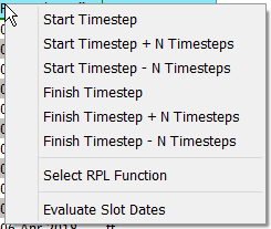
The datetime uses the same syntax as the RiverWare Policy Language (RPL) datetimes. For example, as shown in Figure 4.6, the user could enter either of the following as a valid datetime:
– 24:00:00 November Max DayOfMonth, 1996
– 24:00:00 Start Month Start DayOfMonth, Start Year - 24 Hours
Figure 4.6
See DATETIME in RiverWare Policy Language (RPL) for details on datetimes. Basically, any fully specified datetime can be used
Note: No @ or quotes “ ” are necessary when specifying the datetimes in the DMI slots dialog.
To allow additional flexibility specifying datetimes, the user can choose the Select Function From Global Function Set option and then choose a RPL function from an opened Global Function Set; see Global RPL Functions in RiverWare Policy Language (RPL) for details. A RPL Object selector opens and displays a tree view of all the global utility groups and predefined function groups; see Example: Creating a New RBS Ruleset in RiverWare Policy Language (RPL) for details.

Select a single function by selecting the box to add a check mark. This function MUST:
– Not have any arguments
– Return a fully specified DATETIME variable
If either is not true, an error will be posted when the selection is applied or the DMI is run. After you select Ok, the function name is displayed in the Begin / End column with “( )” appended. Alternatively, you can manually enter the function name, but you must include the “( )”.
Tip: The symbolic datetimes are evaluated for each row in the slot selection when the DMI tree is expanded, the datetime specification is edited, and the DMI is executed. If you change the start/finish timestep, the body of the specified RPL function, or data referenced by the RPL function, the dates won’t automatically update. Use one of the above operations, or to manually evaluate, use the Slots (or right-click context) and then Evaluate Slot Dates menu.
Slots in Selection
The following actions can be performed for Slot Selection rows:
• See the slots that were selected using wildcard.
• See the resolved time interval for each slot, as it will be passed to DSS. See the tip above.
• See the units and scale as they will be passed to DSS.
• For DSS parts, mouse over the slot’s part columns to see the information that will be passed to DSS. The Status at the bottom shows the entire DSS path.
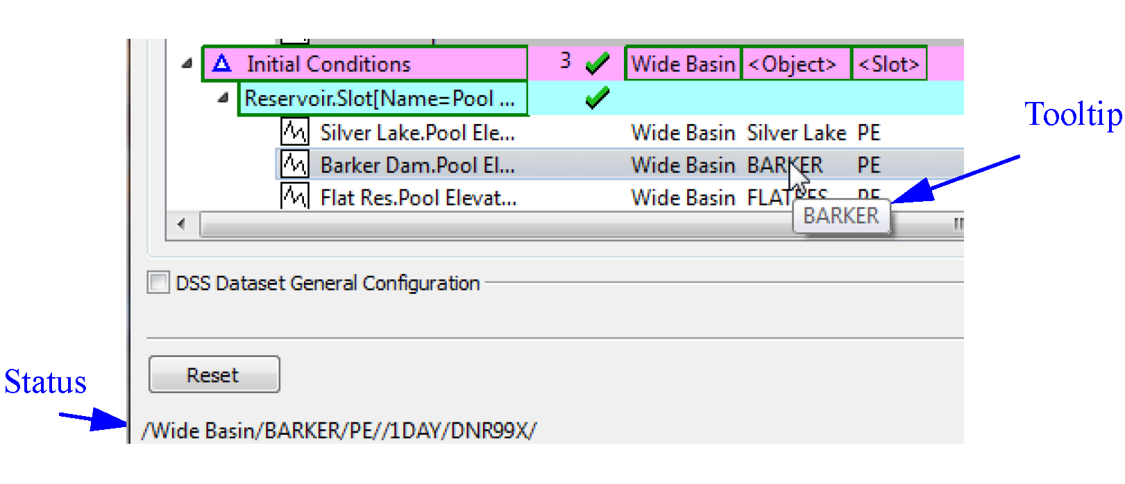
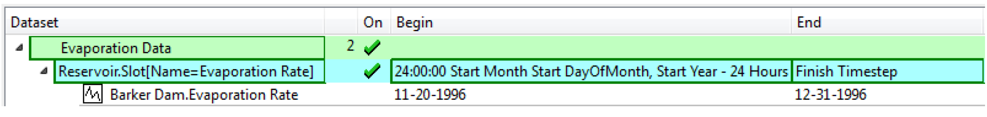
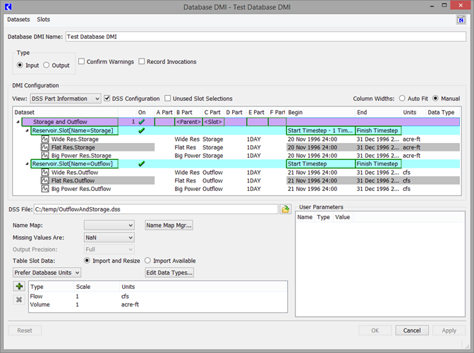
Figure 4.7 shows a fully defined DSS configuration.
Figure 4.7 Screenshot of Database DMI with DSS dataset (left portion)
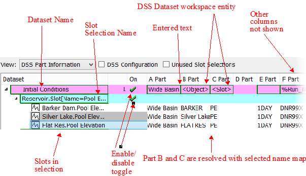
Figure 4.8 shows the right portion of the dialog.
Figure 4.8 Screenshot of Database DMI with DSS dataset (right portion)
Enabling and Disabling for Debugging
Datasets and slot selections can be enabled and/or disabled for debugging purposes. In the On column, there is a green check if it is enabled/on. A red X indicates it is disabled/off. The purpose of this feature is to allow you to debug a DMI by disabling datasets or slot selections and then running the DMI to test other aspects of the DMI. This behaves as follows:
• Turning off a dataset causes its slot selections to be turned off.
• Turning off all slot selections causes the dataset to be shown as off.
• The dataset is shown as a tristate (on/green, off/red, partially on/orange) based on the state of its slot selections.
• The on/off state is preserved in the model file when saved.
Tip: Use the right-click context menu on a slot selection to Turn On this Slot Selection but leave the rest in their current state. This is particularly useful to debug one slot selection. Disable all rows at the top-most dataset level and then use the right-click Turn On this Slot Selection menu to turn on only the desired slot selection row. Similarly, there is a right-click option to Turn Off this Slot Selection.
Use of Name Maps
If you specify a Name Map when configuring the Dataset, then the following will occur:
• If the RiverWare Object is in the Name Map then its mapped name will be used for <Object> or <Parent> entities; otherwise, its RiverWare name will be used.
• If the Slot is in the Name Map then its mapped name will be used for <Slot> entities otherwise, its RiverWare name will be used.
• If a Table Slot column is in the Name Map then its mapped name will be used for Part C; otherwise, the Table Slot’s RiverWare name will be used.
View Columns
Use the View menu in the DMI configuration to select the columns to show.
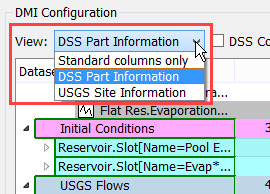
The following options are available depending on the types of datasets in use:
• Standard columns only - The On, Begin, End, and Units columns are shown. These are the only columns available for HDB and Excel Datasets.
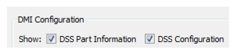
• DSS Part Information - In addition to the standard columns, parts A-F columns are shown. For more information, see DSS Dataset Configuration.
• CDSS Site Information - In addition to the standard columns, Site Name and Site Number columns are shown. For more information, see CDSS Surface Water Time Series - Day.
• USGS Site Information - In addition to the standard columns, Site Name and Site Number columns are shown For more information, see USGS Daily Values.
• CWMS RADAR Name - In addition to the standard columns, a Name column is shown. For more information, see CWMS RADAR Web Service.
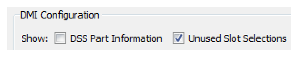
Unused Slot Selections
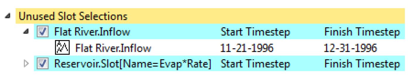
It is possible to have slot selections that are not used by any of the datasets. To show these selections, select Unused Slot Selections.
The selections are then shown as a golden colored row titled Unused Slot Selections at the Dataset level. You can view and change the selections (and the slots selected). From right-click context menus, you can delete the selection. You can also drag and drop the slot selection onto a dataset to associate that slot selection with a dataset.
DSS Dataset Configuration
For DSS datasets, an additional panel allows you to fully edit the dataset.
Note: This is not available for Excel or HDB. For those datasets, you can double-click the dataset and it will open the dataset editor.
When there is a DSS dataset in the DMI, the DSS checkboxes are displayed. Select the DSS Configuration check box to show general configuration settings.
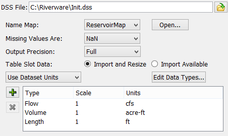
This shows a view similar to the dataset. When you have a DSS dataset selected, the general configuration becomes enabled and allows you to:
• Specify the DSS file for a DSS Dataset.
• Specify the name map using the pull down menu and/or Open the name map manager.
• Specify the desired behavior when missing values are encountered.
• Specify the level of precision for output DMIs.
• Specify the units for the selected DSS Dataset.
• Configure Data Types by selecting the Edit Data Types button.
See Datasets Overview for descriptions of these fields.
Note: Each of these specifications only works on the selected dataset. In other words, you must highlight a dataset row from the middle portion of the dialog before it allows you to change units, scale, name map to use, or how missing values are treated.
Setting Multiple DSS Dataset Files
You can configure the DSS file path for multiple DSS datasets through the Configure DSS Datasets dialog. The dialog is opened by
• Right selecting a DSS dataset in the Database DMI editor dialog and selecting the Set Multiple DSS Dataset Files menu item, or
• Selecting a DSS dataset in the database DMI and then using the Datasets, then Set Multiple DSS Dataset Files menu.
The Configure DSS Datasets dialog appears.
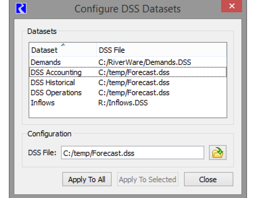
The top portion of the dialog shows all of the DSS Datasets in the model and their DSS File in sortable columns. The bottom portion of the dialog shows the file path for the dataset that was selected when the dialog opened.
Specify an alternative DSS file if desired. Then:
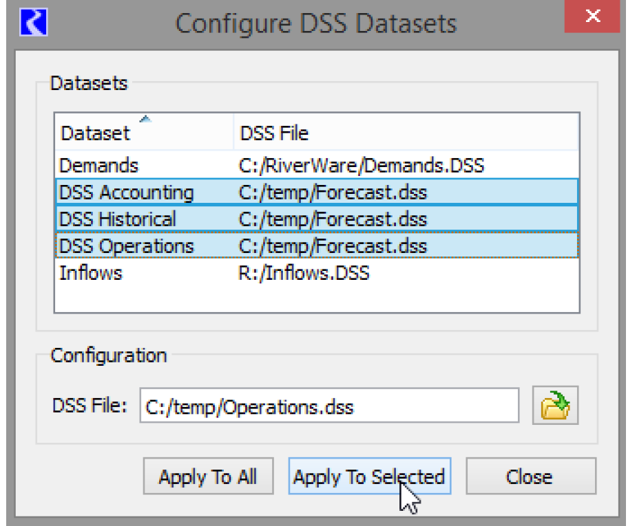
• Select one or more datasets to modify and choose Apply to Selected as shown below.
• Select Apply to All to change every dataset to the new file path.
If a DSS dataset has been modified in another dialog, the DSS file cannot be set. You are notified with the following message: “The following datasets cannot be modified because they are being modified in another dialog”. Apply the changes to that dialog and you can now use the Configure DSS Datasets dialog again.
DSS DMI User Parameters
For DSS, you can specify values to be used for the user parameters. The parameters must be previously configured using the Parameter Dialog; see DMI Parameter Dialog for details.
Edit a parameter value by double-clicking the Value cell to activate a control appropriate for the parameter’s type. To use the parameters in the DSS part information, specify the value with the percent sign; use the following syntax:
%Parameter%
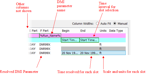
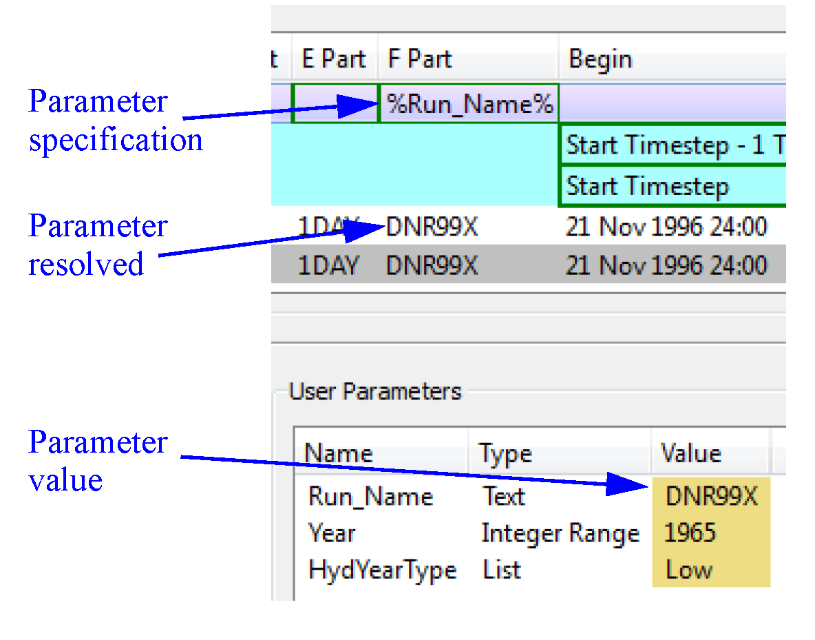
Thus if you have a parameter named Run_Name with a text value and you wanted to put the value in part F, you would double-click part F on the desired Dataset row and type %Run_Name%. In the lower portion, double-click the value column and specify the integer to use. The resolved information is shown for each slot that is a part of the dataset. Figure 4.9 shows this example.
Figure 4.9
Examples
Now that we have described the overall approach for creating a Database DMI, we will present a few example use cases of creating various types of Database DMIs.
Example 1: DSS DMI Using the Database DMI Editor
This example shows how to create a Database DMI to/from DSS using the Database DMI Editor. We assume there are no other Datasets or Name Maps already defined. You would take the following steps:
1. From the workspace, open the DMI Manager using the DMI, then DMI Manager.
2. Create a new Database DMI using the DMI, then New Database DMI menu.
3. Open the Database DMI Editor using the Edit, then Edit menu.
4. In the upper portion of the dialog, enter a name, whether it is an Input or Output DMI, whether to confirm warnings, and whether to record invocations; see Name and Type. Let’s assume we are creating an Output DMI. Leave everything else unchecked.
5. First, add a dataset using the Datasets, then New DSS Dataset menu.
6. Expand the Dataset column and double-click the Dataset0 name and edit it.
7. Next, we will select the slots that we wish to output, say all Reservoir.Storages and Reservoir.Outflows. In the middle portion of the window, right-click the dataset you added, then use the New Slot Selection. A row is added to the tree view below the dataset.
8. Double-click the word NONE to open the slot selector. Use the selector to choose Reservoir.Storage. Add another slot selection and select Reservoir.Outflow. See Creating a Name Map of All Reservoir.Inflow Slots in User Interface for an example of a similar selection.
9. For the Reservoir.Outflow row, specify the timestep by right-clicking once in the Begin field. Choose “Start timestep”. In the End column right-click once and choose “Finish timestep”. For the storage row, repeat and choose “Start Timestep - N” to “Finish Timestep”. Double-click the “N” in the Begin column and type “1” to specify 1 timestep.
10. On the dataset row, right-click in the B Part and select Workspace Entity. Choose <Parent>.
11. On the dataset row, right-click in the C Part and select Workspace Entity. Choose <Slot>.
12. Select the treeview symbol next to the Reservoir.Outflow row to see the exact slots you are going to output and all the part information, timestep, and units. We could change any of the part information by selecting the appropriate column on the Dataset row. For example, we could enter OBS for observed in part F by selecting that field on the dataset row and typing it.
13. Now configure the dataset. Select the dataset row. In the middle of the dialog, select the DSS Configuration toggle.
14. Specify the name of a DSS File in which to send the output either by typing it or using the selector. On an Input DMI, this file must already exist. On the Output DMI, it will be created if it does not exist.
15. If we have already configured a Name Map, we could select that we wanted to use it in the middle portion of the dialog; see DSS Dataset Configuration. A name map is created outside of this dialog; see Name Mapping. Because this is an Output DMI, we do not necessarily have to have a Name Map.
16. Now let’s specify the units to write. In the middle section, select the “+” button. Repeat to add two rows. See DSS Dataset Configuration for details.
17. Double-click the word NONE under the type column to activate the pull-down menu. Choose Volume. On the Units column repeat and choose the desired unit, say Acre-feet. On the second row, Choose Flow and cfs as the units.
18. The Database DMI is now fully configured. Select OK to close the dialog and apply the changes. Invoke the DMI from the DMI manager using the DMI, then Invoke menu.
Figure 4.10 shows the configuration for this example.
Figure 4.10 Screenshot of example DSS DMI
Example 2: Excel DMI to Export Data Using Headers
This example shows how to create a Database DMI to export data to Excel using the Header approach. We assume there are no other Datasets or Name Maps already defined. You would take the following steps:
1. From the workspace, open the DMI Manager using the DMI, then DMI Manager.
2. Choose Utilities, then Datasets
3. Choose Dataset, then New Excel Dataset
4. Double-click the newly created dataset to open it.
5. You will create an output DMI so specify a name in the Name: field. Say “Excel Header PE Sheet”.
6. Select the Excel tab and type in or navigate to a worksheet. Because it is an output DMI and you don’t have an existing sheet, you will have to type in a file name in the selector.
7. Now you will need to choose which approach you wish to use: Ranges or Headers. If you choose Ranges, you will need to create Name Maps. See Slot Mapping—Spreadsheet Ranges Approach for similar samples, based on the configuration. Let’s use the header approach (see Slot Mapping—Header Text and Sheet Names Approach). Select the Map with Header Text and Sheet Names option.
8. You are exporting series slot data, so select the Series Slots option.
9. Specify the Header orientation and specify a sheet name, for example PE. In this sample, use the Timestep, Slots, Runs option.
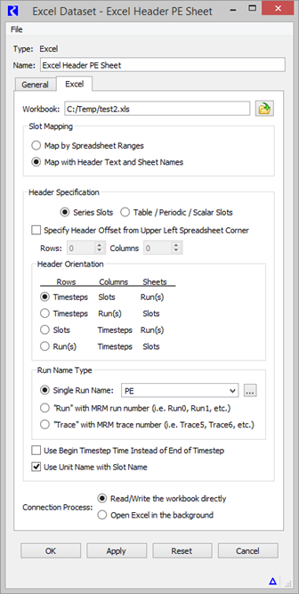
10. Optionally, specify to Use Unit Name with the Slot Name. Figure 4.11 shows the setup for the Excel tab. With this setup, you do not have to use Name Maps, but you could. Thus, we have a fully configured dataset.
Figure 4.11
11. Select OK to accept the changes and close the dialog
12. Back in the DMI Manager, create a new Database DMI using the DMI, then New Database DMI menu.
13. Open the Database DMI Editor using the Edit, then Edit menu.
14. In the upper portion of the dialog, enter a name, that it will be an Output DMI, and whether to confirm warnings. See Name and Type for details.
15. Now add the dataset you configured earlier. Choose Datasets, then Add Existing to open the Dataset Selector dialog.
16. Choose the “Excel Header PE Sheet” dataset and select OK.
17. Next, we will select the slots that we wish to output, say all Reservoir Pool Elevations. With the Excel Header PE Sheet row highlighted, use the Datasets, then New Slot Selection menu.
18. Double-click the word NONE to open the slot selector. Use the selector to choose all Reservoir.Pool Elevations. See Creating a Name Map of All Reservoir.Inflow Slots in User Interface for an example of a similar selection.
19. For the Reservoir.Pool Elevation row, specify the begin timestep by right-clicking once in the Begin field. Choose “Start timestep”. In the End column right-click once and choose “Finish timestep”.
Figure 4.12 shows this setup.
This database DMI is now fully configured. You can execute it from the DMI manager.
Figure 4.12
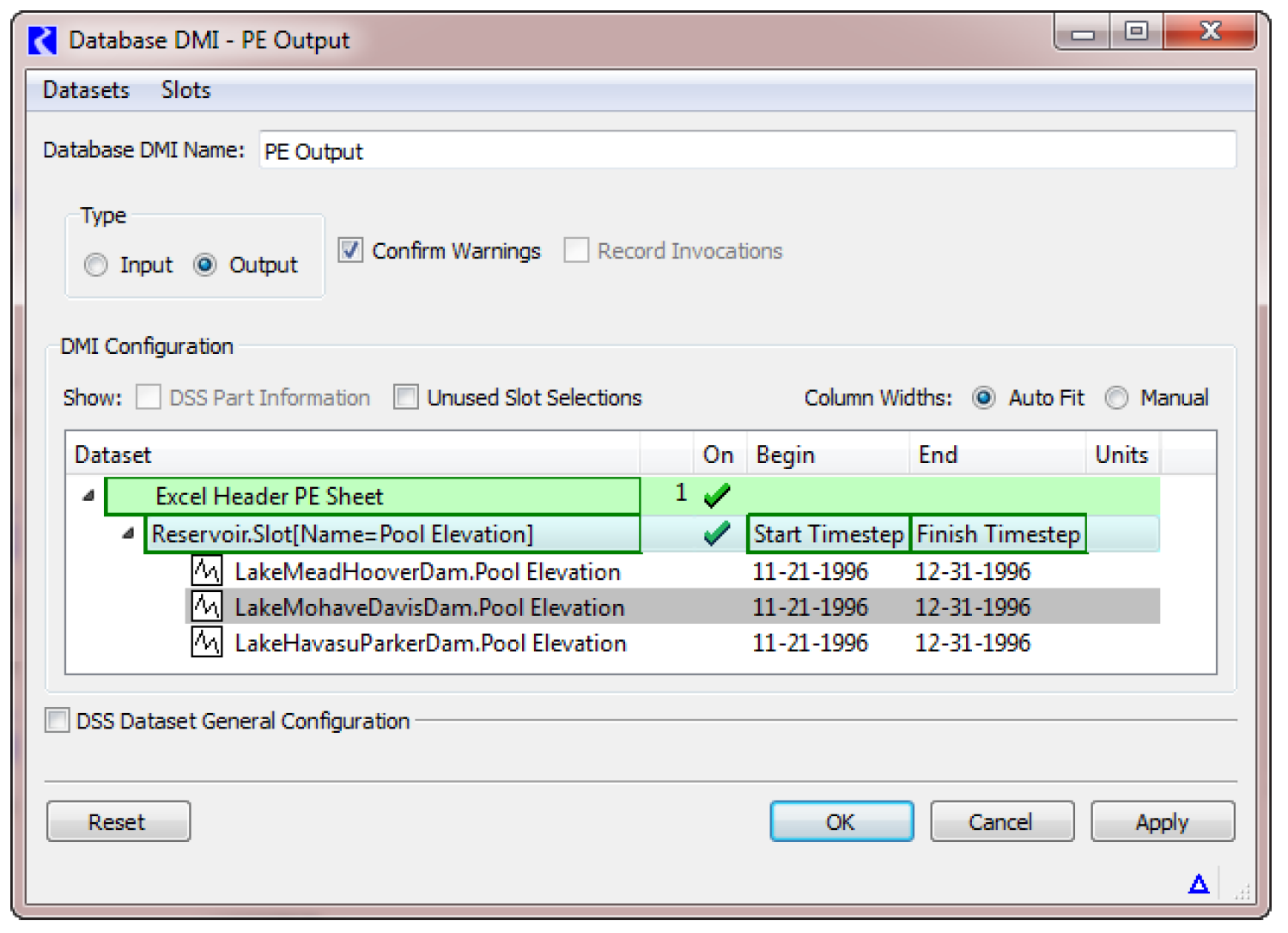
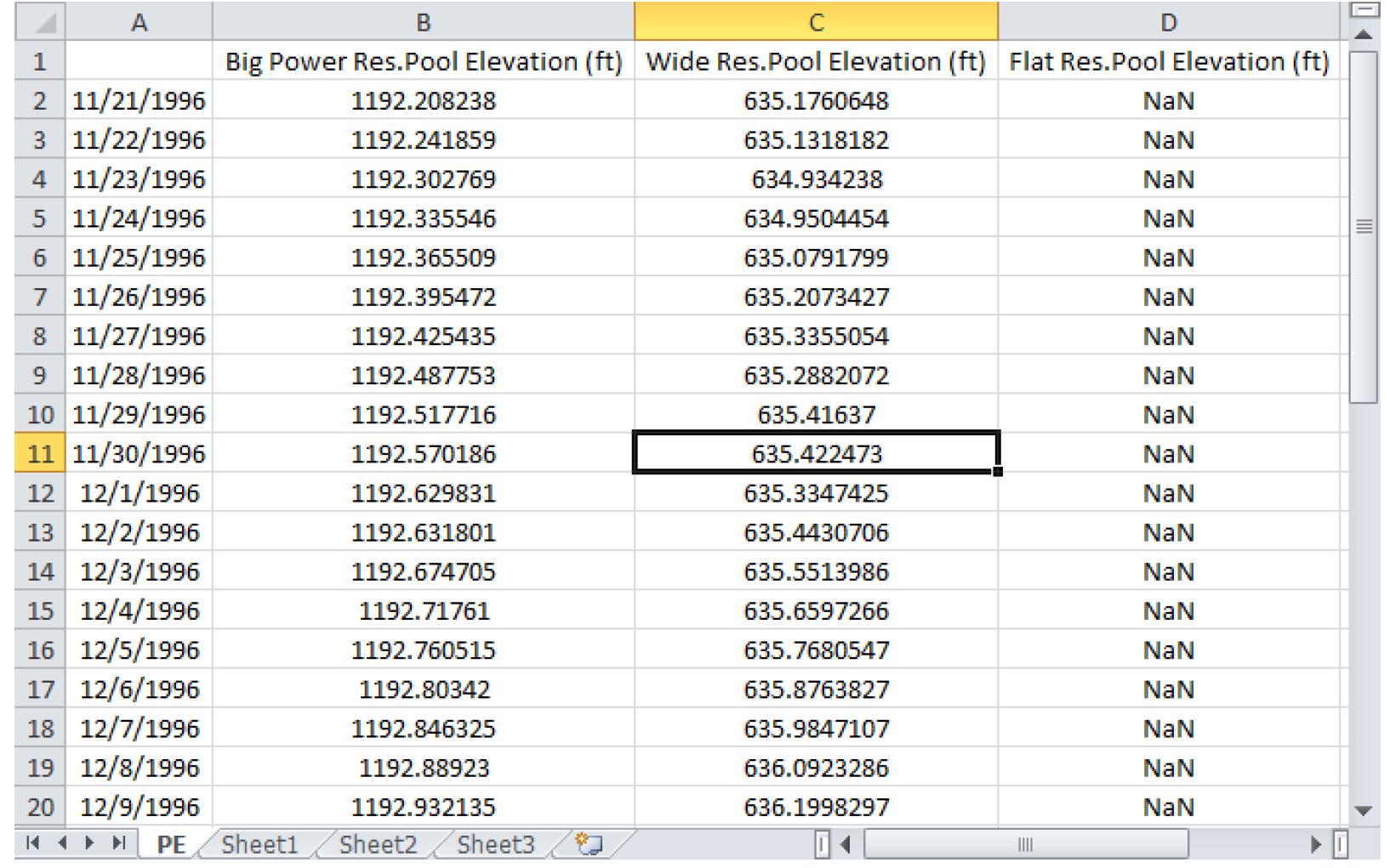
Figure 4.13 shows the resulting spreadsheet for our three-reservoir model.
Figure 4.13
Example 3: Excel DMI to Import Data Using Ranges
This example shows how to create a Database DMI to import data from Excel using the Ranges approach. We assume there are no other Datasets or Name Maps already defined. You would take the following steps:
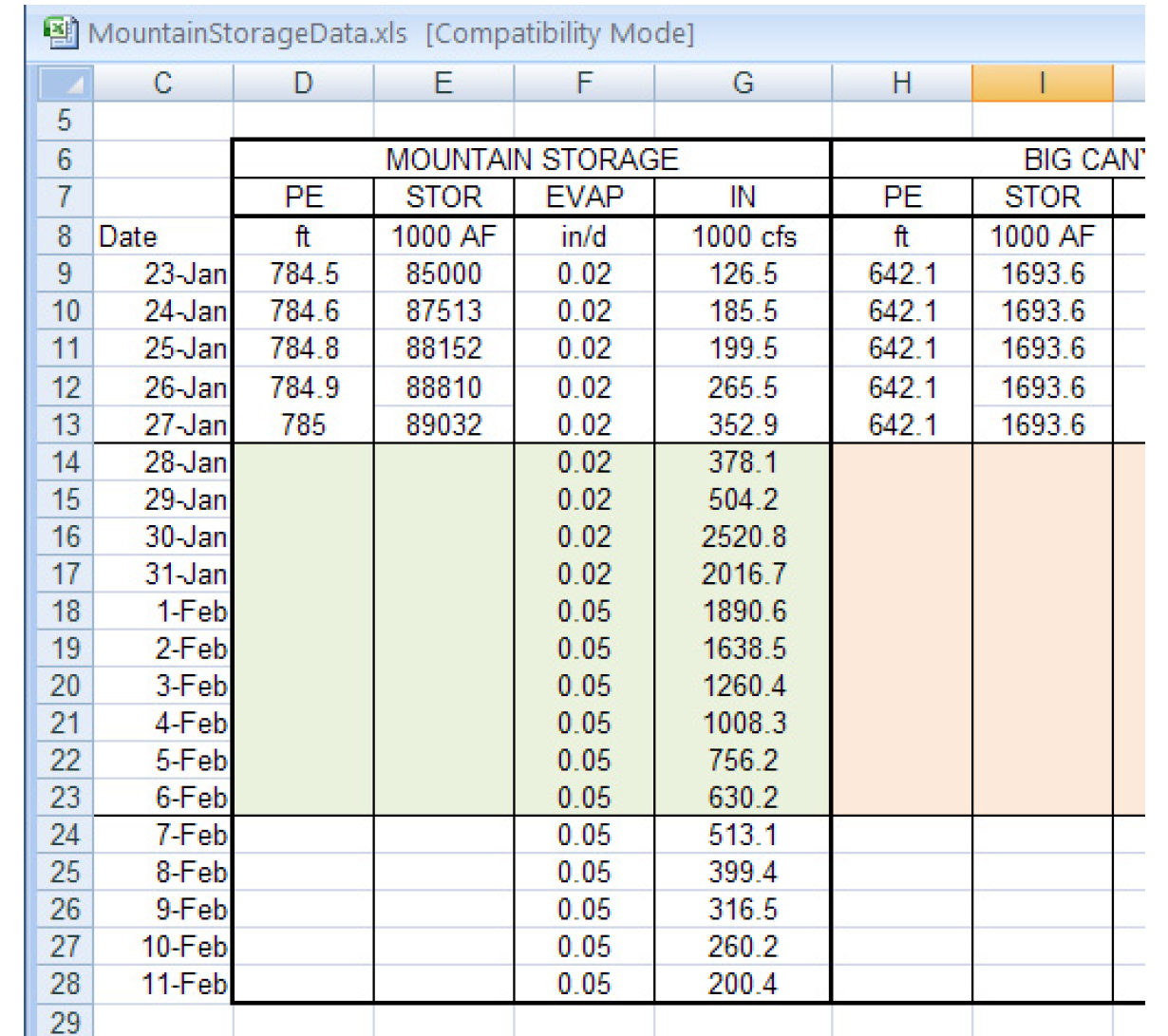
1. Figure 4.14 is screenshot of the desired data in Excel. It is not in the format necessary for the Headers approach. So we will use the Ranges approach. We would like to import the Mountain Storage IN column to the slot Mountain Storage.Inflow for just the run range (Jan 28-Feb 6th). That is, we want to import the range G14:G23.
Figure 4.14
2. From the workspace, open the DMI Manager using the DMI, then DMI Manager.
3. From the DMI Manager choose Utilities, then Name Maps.
4. Choose Name Map, then New or select the + button.
5. Double-click the newly created Name Map.
6. Change the name to “Mountain In”
7. Select Name Map, then New to add a row to the list.
8. Click-pause-click on the word NONE and choose Select Slot.
9. Using the selector, choose the reservoir slot Mountain Storage.Inflow. Select OK.
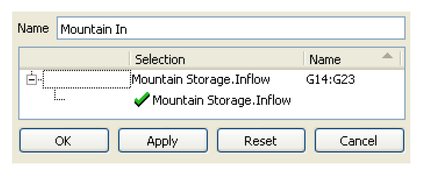
10. In the Name Map, in the Name column type “G14:G23” (without quotes).
11. Select OK in the Name Map and OK/Cancel in the Name Map Manager to close.
12. In the DMI Manager, choose Utilities, then Dataset.
13. Choose Dataset, then New Excel Dataset.
14. Double-click the newly created dataset to open it.
15. You will create an input DMI so specify a name in the Name: field: “Input Mountain Inflow”.
16. In the Name Map section, choose the Name Map you created “Mountain In” from the pull down menu.
17. Select Units, then New
18. Under the Type column, click-pause-click and choose Flow from the pull down menu.
19. Change the Scale to 1000 and the Units to cfs.
20. Select Apply.
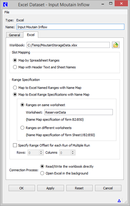
21. Select the Excel tab and type in or navigate to the worksheet where the data resides. In the sample, it is in C:/Temp/MountainStorageData.xls.
22. Select the Map by Spreadsheet Ranges button.
23. Choose the Map to Excel Range Specification with Name Map.
24. The data is all on the same worksheet and we didn’t enter it in the Name Map, so you will need to enter it here. In the Worksheet field, enter the name of the sheet, “ReservoirData”.
25. The dataset is fully configured, as shown in Figure 4.15. Select OK to apply and close the dialog.
Figure 4.15
26. Back in the DMI Manager, create a new Database DMI using the DMI, then New Database DMI menu.
27. Open the Database DMI Editor using the Edit, then Edit menu.
28. In the upper portion of the dialog, enter a name and that it will be an Input DMI. See Name and Type for details.
29. Now add the dataset you configured earlier. Choose Datasets, then Add Existing to open the Dataset Selector dialog.
30. Choose the Input Mountain Inflow dataset and select OK.
31. We will select the slots that we wish to input. With the Input Mountain Inflow row highlighted, select Datasets, then New Slot Selection menu.
32. Double-click on the word NONE to open the slot selector. Use the selector to choose Mountain Storage.Inflow.
33. For the Mountain Storage.Inflow row, specify the timestep by right-clicking once in the Begin field. Choose “Start timestep”. In the End column right-click once and choose “Finish timestep”.
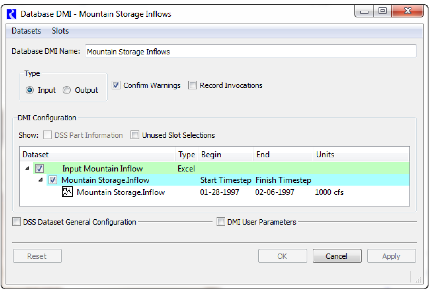
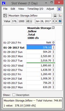
34. This database DMI is now fully configured. You can execute it from the DMI manager. Figure 4.16 shows the resulting slot.
Figure 4.16
Revised: 06/04/2022