
RiverSMART User’s Guide
Using RiverSMART
Topics
Installing and Starting RiverSMART
RiverSMART is included as part of the RiverWare installation. Install RiverWare and RiverSMART will be installed in the same location as RiverWare.
Note: In version 8.5 and before, the installation of RiverSMART and RiverWare were separate and the RiverSMART study and RiverWare Event had a reference to the location of RiverWare. In version 9.0, RiverWare and RiverSMART are bundled and installed together. The RiverWare version and RiverSMART version are then automatically the same.
To start RiverSMART, use the desktop shortcut icon or locate RiverSMART.exe in the installation folder and double click to start it:
Starting a Study
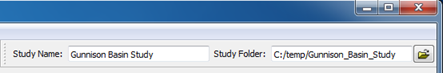
When you start a new RiverSMART study, you must assign a study name and the Study Folder, which is the folder where the study and all its subfolders are written. Environment variables can be used in the Study Folder path; if used, they must be preceded by a $ symbol.
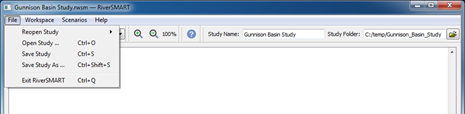
The File menu includes options for saving the study, opening an existing study, and exiting RiverSMART.
The RiverSMART Help item on the Help menu displays this Help document.
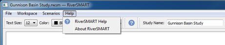
The Help  button in the toolbar also opens the RiverSMART Help.
button in the toolbar also opens the RiverSMART Help.Note: Each event configuration dialog box includes context-sensitive Help; see “Events” for details.
Study Folder Structure
An important aspect of RiverSMART is its ability to manage all files associated with a complex study. The Study Folder, which you specify when you create a study, is the root for all subfolders and files; see “Installing and Starting RiverSMART” for details.
RiverSMART automatically creates the following folders under the Study Folder. This self-contained folder structure makes it easy to archive or move the entire study.
Hydrology\
This folder includes a subfolder for each hydrology event in the study, identified by event name. Hydrology event types include Hydrology Simulator, Spatial Disaggregation, and Temporal Disaggregation. Each event folder includes the trace folders for the ensemble of data generated by the event.
Model\
RiverSMART creates this folder but places nothing in it. This folder is where the user puts all study input files that are not generated by RiverSMART, such as RiverWare model files, rulesets, input DMI data and control files, hydrology event inputs, GPAT configuration files, and RDF Annualizer control files.
Scenario\
This folder includes a subfolder for each activated scenario in the study, identified by scenario name. Each scenario folder includes the result files generated for the scenario, including RDF files from RiverWare, RDF files from RDF Annualizer, and Excel files from RDF To Excel.
ScenarioSet\
This folder includes a subfolder for each scenario set processed. Within each scenario set folder, there are folders for each event that processes the scenario set. Each event folder includes the result files generated by the event while processing the set.
Working\
This folder includes a subfolder for each event that was processed in the study, identified by the event name. Each event folder includes log files, XML files, and intermediate result files generated while processing the event. This information can be useful in debugging problems that occurred during processing.
Using the RiverSMART Workspace
The RiverSMART workspace is populated with events, files, and links to create a study. These study building blocks are discussed in the following sections.
Events
RiverSMART is essentially a framework for communication between independent processes or programs, which are called events. On the software level, each event is actually an independent program called a plugin, and an event is an instance of a plugin.
To add an event to the workspace, right-click the workspace; in the shortcut menu, select Add Event and then the event you want to add.
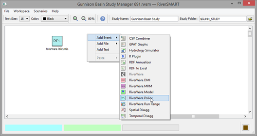
When an event is added to the workspace, it is shown as an icon representing the event type. Following are descriptions of the available events, categorized by function.
RiverWare Event
 RiverWare
 Displays the version of RiverWare used for the study and allows for some options. There must be exactly one RiverWare event per study.
See “RiverWare Event” for details.
Hydrology Events
Hydrology events allow you to create traces of hydrology data that can be moved into RiverWare through a specified RiverWare Data Management Interface (DMI) event.
 Hydrology Simulator
 Synthesize an ensemble of hydrologic traces at an annual timestep based on observed streamflow values and a user-selected algorithm.
See “Hydrology Simulator Event” for details.
 Spatial Disaggregation
 Disaggregate an annual ensemble of flow data for a site into ensembles for multiple sites.
See “Spatial Disaggregation Event” for details.
 Temporal Disaggregation
 Disaggregate an annual ensemble of flow data for a site into a monthly ensemble for the site.
See “Temporal Disaggregation Event” for details.
RiverWare Input Events
Input events allow you to configure inputs to the model and options for generating scenarios.
Note: The combination of DMIs, models, MRM configurations, and RiverWare policies are user-selectable through the Scenario Organizer dialog box.
 RiverWare DMI
 Specify a DMI to use in importing data into the RiverWare model. The input can be a single series, imported before the multiple runs are executed, or it can be trace-based, run as an ensemble. For example, the outputs of the Hydrology Simulator or Demand Input Tool (DIT) can be input to RiverWare through the DMI event.
See “RiverWare DMI Event” for details.
 RiverWare DMI Sequence
 Specify a sequence of RiverWare DMIs, such as initial conditions, to use in importing data.
See “RiverWare DMI Sequence Event” for details.
 RiverWare Model
 Specify the name and location of a RiverWare model file to use in generating scenarios.
See “RiverWare Model Event” for details.
 RiverWare MRM
 Specify an MRM configuration defined in the RiverWare model to use in generating scenarios.
See “RiverWare MRM Event” for details.
 RiverWare Policy
 Specify a RiverWare Policy Language (RPL) policy set, and optional global function sets, to use in generating scenarios.
See “RiverWare Policy Event” for details.
 RiverWare Run Range
 Configure run ranges, and an optional R script to adjust the run ranges, to use in generating scenarios. You can configure multiple Run Range events to generate scenarios with different run ranges, such as different start dates, end dates, or timesteps.
See “RiverWare Run Range Event” for details.
Post-processing Events
Post-processing events allow you to configure options for processing study results.
 CSV Combiner
 Combine comma-separated value (CSV) output data from all scenarios in a scenario set into a single CSV file.
See “CSV Combiner Event” for details.
 or
or  GPAT Graphs
 Execute a specified GPAT Graphs configuration file to generate statistical graphs from Microsoft Excel files that include series data for selected scenarios or scenario sets. The graphs can be written to an Excel workbook.
See “GPAT Graphs Event” for details.
 or
or  R Plugin
 Call user-created R programming language scripts to post-process study results for selected scenarios or scenario sets.
See “R Plugin Event” for details.
 RDF Annualizer
 Aggregate data from an RDF file with a less-than-annual timestep, to produce an RDF file with an annual timestep.
See “RDF Annualizer Event” for details.
 RDF To Excel
 Convert output data from an RDF file to an Excel workbook according to a user-defined workbook configuration.
See “RDF To Excel Event” for details.
General Event Configuration Dialog Box Fields
To open the Configuration dialog box for an event, double-click the event icon on the RiverSMART workspace. Following is a sample Configuration dialog box for a RiverWare DMI event.
Note: You cannot configure events and files while also generating, simulating, and post-processing scenarios. If a dialog box for processing scenarios is open in the RiverSMART workspace, you cannot open the configuration dialog box for an event or file.
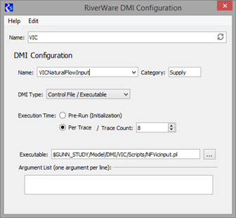
Name
This field is common to all event Configuration dialog boxes. This entry must be unique among all events in the study. A unique name is automatically generated when an event is created, and you can replace it with a user-defined descriptive one.
This entry is displayed on the workspace as a label directly below the event icon; therefore, it should be descriptive but not too long. This entry is also used as a folder name by RiverSMART when it manages files related to the event.
Help
This menu is common to all event Configuration dialog boxes. The Help selection displays a context-sensitive Help topic to assist you in completing the configuration dialog box.
Placeholder events
This option is available for input-type events: DMI, MRM, Policy, and Model. Sometimes, the choice of inputs in a study is not just between the type of inputs—for example, high or low demand—but between input or no input—for example, between Supplemental Flow A or no supplemental flow. For these cases, RiverSMART allows you to designate an input event as a placeholder. To do so, select Edit, then Placeholder in the DMI, MRM, Policy, or Model Configuration dialog box.
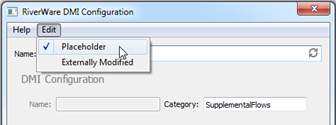
When an event is designated as a placeholder event, all its configuration options are disabled, except the Name and Category fields for DMI events. The placeholder event is treated as any other input event in its category when scenario combinations are generated; see “Generating Scenarios” for details. When the scenarios are executed, however, the event does nothing. For example, a placeholder DMI event does not invoke any DMI for its category when a scenario that includes the placeholder DMI event is simulated.
Deleting events
To delete an event from the workspace, right-click the event icon on the RiverSMART workspace and select Delete Event from the shortcut menu; alternatively, select the event and press Delete.
Files
File items specify file names for outputs from events. When linked to a following event, a file item specifies an input file name for that event.
File Configuration Dialog Box Generic Fields
To add a file to the RiverSMART workspace, right-click the workspace, select Add File on the shortcut menu, and then select the file type. The following file types are available.
 RiverWare Data File. ASCII file representing slot data from RiverWare, typically output to capture data from all traces of a multiple run.
  Microsoft Excel Workbook File. Excel workbook, which may be an output from the RDF To Excel event, or input or output to a GPAT Graphs event.
  CSV File. Comma Separated Values file representing slot data from RiverWare, typically output to capture data from all traces of a multiple run.
  netCDF File. Network Common Data Form file representing slot data from RiverWare, typically output to capture data from all traces of a multiple run.
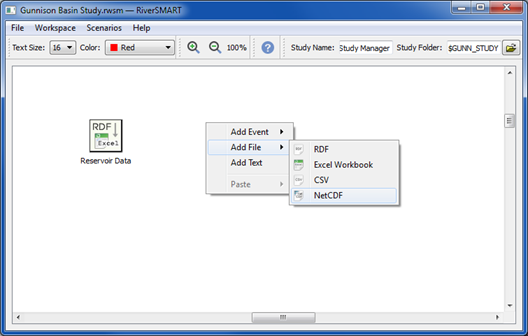
To open the Configuration dialog box for a file, open the file icon on the RiverSMART workspace. Following is a sample Configuration dialog box for an RDF file.
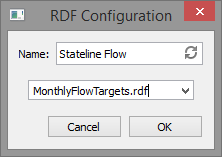
Name
This is the label that appears on the RiverSMART workspace below the file icon. This field is common to all file Configuration dialog boxes.
The default entry is the descriptive file type, such as RDF or Excel Workbook. You can override this by entering a user-defined label in the Name text box. This entry does not need to be unique.
Filename
To assign the file name, you can enter it in the text box or select it from the menu. The menu lists all files of the applicable type in the model MRM output configurations.
Note: You enter just the file name, not the full path; the full path to an instance of the file is determined by RiverSMART when it processes a scenario.
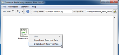
Deleting a file
To delete a file from the study, right-click the icon on the RiverSMART workspace and select Delete File from the shortcut menu; alternatively, select the file and press Delete.
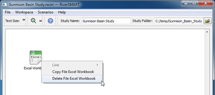
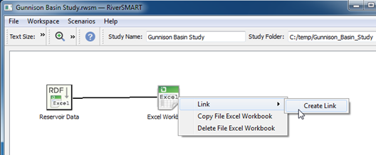
Linking
You create links on the workspace to represent how information flows between events and files. The link arrow indicates the direction of the link.
In some cases, you can link an event directly to another event; but in cases where the event output is preserved as a file, you can link the event to a file item, which can then be linked to a following event. Hydrology events link directly to each other; RiverWare input events link directly to RiverWare; and post-processing events link through file items.
To create a link, right-click an event or file, select Link in the shortcut menu, and then use one of the following methods.
• The menu lists destinations that are valid for the starting item based on the valid inputs and outputs for its file type and the permitted number of input and outputs. If you select a destination from the menu, the link is automatically created between the starting item and the selected destination item.
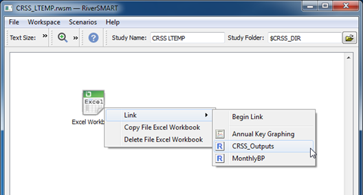
• If you select Begin Link, a black rubber-banded line is attached to the starting item; then as you hover over other events or files, the line turns green if it is a legitimate destination, or red if it is not. To complete the link, right-click a legitimate destination and select Create Link in the shortcut menu.
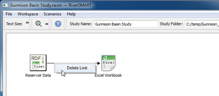
To delete a link, right-click the link line and select Delete Link in the shortcut menu; alternatively, select the line and press Delete.
Adding Text
You can add text to the workspace to identify items that can be grouped together, or to add other information.
To add text, right-click the desired location on the workspace and select Add Text in the shortcut menu. Enter the desired information in the text configuration dialog box. Line beaks will be respected. Click OK to close the Text Configuration. You can drag the text to any location on the workspace. To edit the text, double click to open the text box. To delete the text, right-click the text box and select Delete Text in the shortcut menu; alternatively, select the text and press Delete.
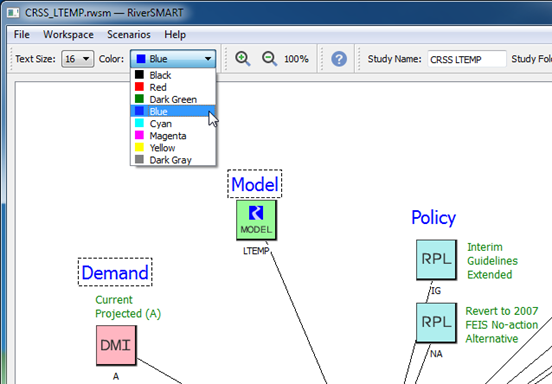
You can select one or more text items and use the controls in the workspace toolbar to modify their color and font size. Any new text added to the workspace uses the font size and color selected in the toolbar.
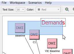
Multiple Selection
Use one of the following methods to select multiple events, files, or text items.
• Click and drag over the items.
• Ctrl+click multiple items.
When you right-click the selected items, the shortcut menu applies to all selected items.
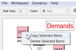
Copy and Paste
You can copy selected events, files, and text items to the system clipboard, and then paste them anywhere in the current study. The spatial relationships among the selected items are preserved, as are any links.
To copy items to the system clipboard, right-click the selected items and select Copy from the shortcut menu. The exact wording of the Copy option varies according to the selected items.
To paste items from the system clipboard to the current study, right-click the workspace and select one of the following options from the shortcut menu.
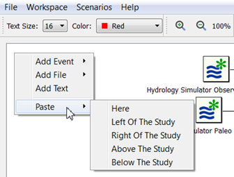
• Here—Pastes the items at the current cursor position, which is the upper-left corner of the pasted items.
• Left of the Study—Pastes the items centered on the left border of the study.
• Right of the Study—Pastes the items centered on the right border of the study.
• Above the Study—Pastes the items centered on the top border of the study.
• Below the Study—Pastes the items centered on the bottom border of the study.
After you paste the items, they remain selected so you can adjust their placement.
You can also copy and paste items to and from external applications that support the system clipboard; for example, text editors and email clients.
File Menu
The File menu in the RiverSMART menu bar includes menu items to open and save study files. The Reopen Study menu lists the six most recently opened study files and folders.
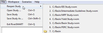
You can select files and folders by selecting them on the menu or by entering their number. Selecting a file opens the study file, and selecting a folder opens the File Chooser in the folder.
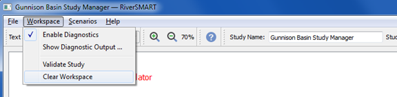
Workspace Menu
The RiverSMART Workspace menu includes options for controlling the collection and display of diagnostic messages, validating the configurations of the events and files in the workspace, and clearing the workspace.
Diagnostic messages are displayed in the RiverSMART Diagnostics dialog box, and they are color-coded as follows:
• Black—informational
• Gold—warning
• Red—error
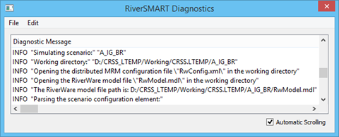
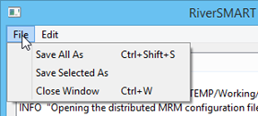
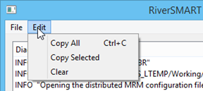
The Diagnostics File and Edit menus include options to save diagnostic messages to a file, copy diagnostic messages to the system clipboard, and clear all diagnostic messages.
The Validate Study option on the Workspace menu validates the configurations of the events and files shown on the workspace. Validation varies with the event or file, but generally includes verifying that required configuration information is provided and that referenced files that should already exist are available and readable.
Validation messages are displayed in the Study Validation dialog box, and they use the same color coding as diagnostic messages.
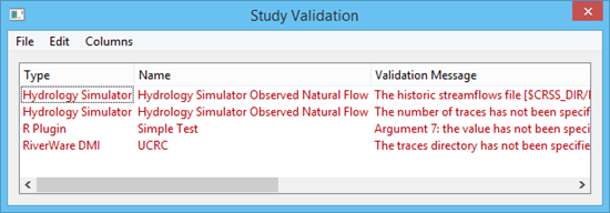
The Study Validation File and Edit menus provide the same options as the Diagnostics dialog box.
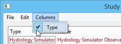
The Study Validation Column menu hides or shows the Type column.
The Clear Workspace option on the Workspace menu removes all events, files, links, and text from the workspace.
Workspace Zoom
Controls on the toolbar allow you to zoom in and out of the workspace in increments of 10 percent, within the range of 10%–400%. The current zoom percent is displayed next to the controls.

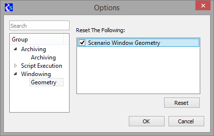
Scenario Window Geometry
The size and location of the four scenario dialog boxes—confirmation, organization, simulation, and post-processing—are saved so they always open using the same size and placement on the workspace. This geometry persists across RiverSMART sessions.
To reset the window geometry to the default settings, select Workspace, then Options; alternatively, select the Options button on the RiverSMART toolbar.
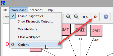
In the Group area of the Options dialog box, select Windowing, then Geometry. Under Reset the Following, select the Scenario Window Geometry check box, then select Reset.
Status Bar
The Status Bar, near the bottom of the workspace, includes the following elements.
• Study status area (blue background). For example, “Executing event RiverWare”.
• Event status area (green background). For example, “Simulating scenario C Inflow 2, E Inflow2, R Inflow1, T Vs, CRSS Policy 2”.
• Event progress bar. This displays the percent complete if the event is able to do so; otherwise, this bar functions as a busy indicator.
• Diagnostic Window. This button provides a graphical indication of whether there are warning or error messages that have not yet been viewed by users. Not yet viewed means users have not opened the RiverSMART Diagnostic window since the messages were posted. You may need to scroll the Diagnostic window to view the messages.
– Normally, this button displays a Log File icon.
– If the Diagnostic window includes warnings that have not yet been viewed, the button changes to the warning color and blinks.
– If the Diagnostic window includes errors that have not yet been viewed, the button changes to the error color and blinks.

RiverSMART Workspace
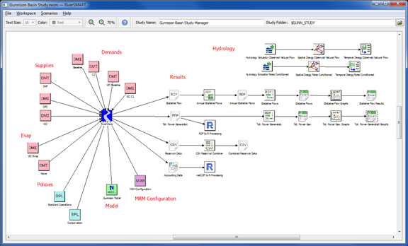
Figure 2.1 is a sample configured workspace with events, files, and links. This example study shows two sets of hydrology events, which are linked in the upper-right portion of the workspace.
Only one RiverWare event is allowed in a study. In the example, RiverWare inputs are linked to RiverWare, on the left side of the workspace, with DMIs grouped into Demands, Supplies, and Evap. RDF files coming out of RiverWare are post-processed through a series of events and files, on the right side of the workspace, to produce GPAT graphs in Excel workbooks.
Figure 2.1 Sample configured RiverSMART workspace
Approaches for Setting Up RiverWare Inputs
When you configure a study, you must consider what to configure in the RiverWare model versus what to configure as inputs in RiverSMART. This is particularly true for MRM and DMI configurations.
MRM configurations in RiverWare can specify initialization and per-trace DMIs, as well as policy. One approach is to create a RiverSMART event for a RiverWare MRM configuration that includes these components and not include the DMIs and policy as events on the RiverSMART workspace. This hides the scenario components, however, and prevents them from being displayed in RiverSMART. To view the DMIs and policies, you need to open the RiverWare model, which reduces the usefulness of RiverSMART for visualizing how inputs are combined into scenarios.
A more transparent approach is to create DMI and policy events in RiverSMART to be paired with an MRM configuration event. RiverWare substitutes the DMIs and policy configured in the RiverSMART events into the MRM configuration to create the scenarios. In this approach, the RiverSMART workspace provides a visual representation of how the scenario components are combined into scenarios.
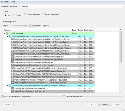
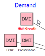
As an example of DMI configuration trade-offs, consider the four demand DMIs in Figure 2.1. These could be Excel Database DMIs, in which the data for each demand is included on a separate worksheet in an Excel workbook.
One approach would be to set up four DMIs in RiverWare and have each DMI event in RiverSMART refer to one of the RiverWare DMIs by name. To set up the DMIs in RiverWare, you would need to repeat much of the same configuration information four separate times: you would need to repeat the Excel dataset configurations, each of which specify a different worksheet in the same Excel workbook, for each DMI; more importantly, you would need to repeat the slots into which the demand data is imported. This would involve possibly hundreds of slots, and it would be a tedious and error-prone process to keep their begin dates, end dates, and units consistent across all DMIs. Figure 2.2 shows a sample RiverWare configuration of an Excel Database DMI with slot selections.
Figure 2.2 Sample RiverWare configuration of Excel Database DMI
A better approach is to create one dataset and one DMI in RiverWare, to serve as a template for RiverSMART to use for each scenario. You can configure the Excel dataset to refer to the Excel workbook, leaving the Single Run Name (worksheet name) blank, as shown in the following figure.
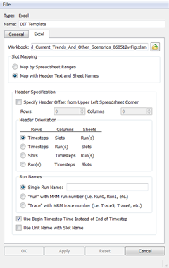
The RiverWare DMI then uses this template dataset, including the slot selections shown in Figure 2.2. The four RiverSMART DMI events refer to the RiverWare DMI, but each specify a different worksheet name to be substituted into the template dataset for that particular demand, as shown in the following figure.
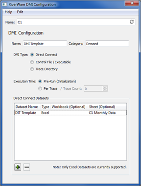
Using this approach, you need to maintain just one dataset and one DMI in RiverWare. RiverSMART can use these as a template and substitute the correct worksheet for each demand as configured in its DMI events. A disadvantage of this approach is that you cannot run the demand DMIs interactively from RiverWare without inserting the missing information into the template manually or through a script.
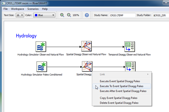
Using Hydrology Processing Events
The hydrology-related events link to one another, but not to other types of events. Their purpose is to create traces of hydrology data that can be moved into RiverWare through a separately configured RiverWare DMI event. Generating hydrologies can be time-consuming, and once configured properly, these events are not typically rerun unless some input data has changed.
Note: For hydrology events to execute successfully, the R Project for Statistical Computing must be installed on your computer; see “Install R and Component Packages” for details.
To execute a hydrology event, right-click the event and select one of the execution options from the shortcut menu. You can execute just the selected event, all previous linked events up to and including the selected event, or all events after the selected event. These options provide flexibility for executing a linked hydrology sequence, allowing you to rerun just the parts you need.
Study Folder Structure for Hydrology Results
RiverSMART saves all generated hydrology results to the Study Folder you have specified, using the following structure.
Study_Folder\
Hydrology\
event_name\
trace_name\
generated data files
trace_name\
generated data files
event_name\
trace_name\
generated data files
trace_name\
generated data files
Working\
event_name\
log files
intermediate results
event_name\
log files
intermediate results
• The Hydrology\ folder includes a folder for each event that generates hydrology data.
– Within each event folder, there are trace folders that include the generated data files for each trace.
• The Working\ folder also includes a folder for each event.
– Within each event folder, there are log files and intermediate results, which may be useful for debugging problems in event execution.
Simulating Scenarios
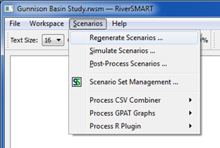
A scenario is a specific combination of RiverWare inputs that create a RiverWare run. The generation, simulation, and post-processing of RiverWare scenarios are controlled from the Scenarios menu in RiverSMART.
Note: These menus are disabled if any Configuration dialog boxes are open for files or events on the workspace; configuring and running scenarios are mutually exclusive actions.
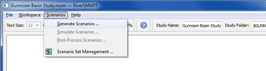
Generating Scenarios
The Scenario List Organizer dialog box allows you to define scenarios from all potential combinations of inputs linked to RiverWare. To open this dialog box, select Scenarios, then Generate Scenarios on the RiverSMART menu.
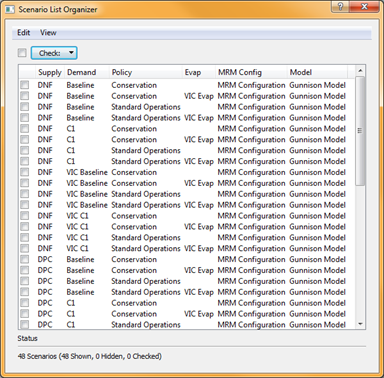
A column is created for each RiverWare input category. In the example, the RiverWare DMIs have been assigned one of three category names in their configuration dialog boxes, so these categories show up as separate columns: Supply, Demand, and Evap.
The scenario name is automatically formed by concatenating the column names from left to right. By default, the columns are displayed in alphabetical order, but you can drag them into any order that is useful for identifying the scenarios.
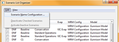
You can make additional changes to scenario names by selecting Edit, then Scenario Name Configuration.
The Scenario Name Configuration dialog box allows you to select the columns to include in the scenario name. It also allows you to define the separator between the components.
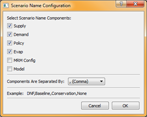
In this example, the same MRM Configuration and Model are used for all scenarios, so including them in the name adds no meaningful information to help differentiate among scenarios. The check boxes for these elements are therefore cleared to exclude them from the name. A comma is selected as the separator in the Components Are Separated By menu. An example scenario name is displayed at the bottom of the dialog box.
Caution: When you generate scenarios, RiverSMART assigns the scenario names to the folders it creates for the generated files. Therefore, if you make changes to the scenario names after you generate scenarios, all simulation and post-processing state information associated with the previous names are lost when the scenarios are regenerated.
The Scenario List Organizer indicates that 48 scenarios have been created from the combination of inputs to RiverWare. Not all of these combinations are meaningful, however—for example, VIC Evap should only be used with VIC supplies. Only 12 scenarios among the 48 should be run for this model.
Hiding and Deactivating Scenarios
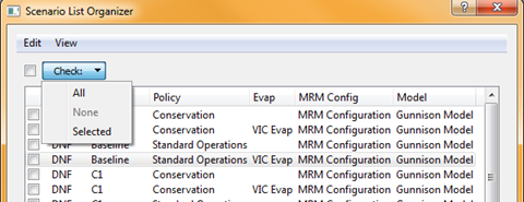
To eliminate unwanted combinations from all dialog boxes, you can select the unwanted scenarios and deactivate them. To select scenarios, select Check and then one of the following options:
• All—selects all rows (scenarios); this is equivalent to selecting the Check check box.
• None—clears all rows.
• Selected—selects the selected rows; this is equivalent to selecting individual row check boxes.
Once you have selected unwanted scenarios, you can deactivate them by selecting Edit, then Deactivate Checked Scenarios. When a scenario is deactivated, it is made unavailable throughout RiverSMART and is not displayed in any RiverSMART dialog boxes.
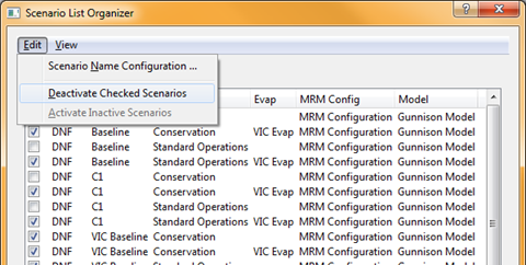
If you deactivate a scenario by mistake, you can reactivate all scenarios by selecting Edit, then Activate Inactive Scenarios. You can then select the correct ones and deactivate them.
You can also dynamically hide and show active scenarios in the current dialog box. Hiding a scenario does not deactivate it; it simply hides the scenario in the current dialog box and does not affect other dialog boxes.
To hide active scenarios, select the rows, then select View, then Hide Checked Scenarios. To show all active scenarios, select View, then Show Hidden Scenarios.
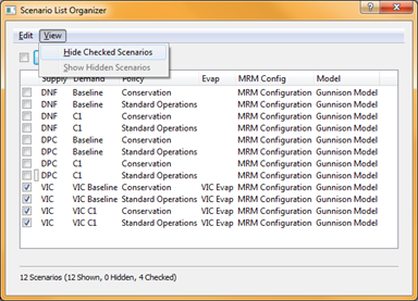
The status line at the bottom of the dialog box displays the number of scenarios active, shown, hidden, and currently selected.
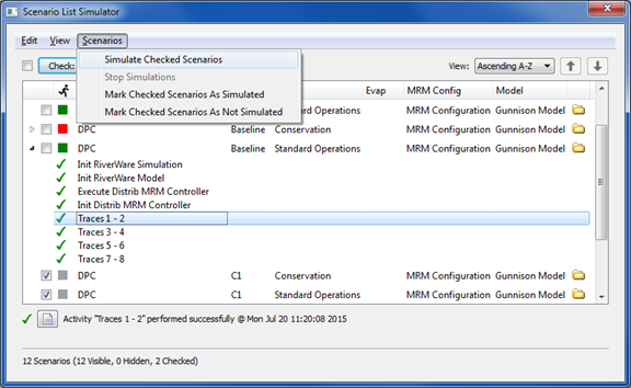
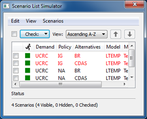
Simulating Scenarios
The Scenario List Simulator dialog box displays a two-level tree view that lists the activated scenarios at the top level. Within each scenario, the activities that have been completed during simulation are listed. To open this dialog box, select Scenarios, then Simulate Scenarios on the RiverSMART menu.
To initiate a RiverWare MRM run using the scenario inputs, select the scenario check box, and then select Scenarios, then Simulate Checked Scenarios.
MRM runs are typically set up as distributed runs. If they are not set up that way, they are automatically converted into distributed runs using the default number of processors on the machine. If you select more than one scenario in the Scenario List Simulator, each one runs sequentially until all are completed.
If you need to halt execution while scenarios are running, select Scenarios, then Stop Simulations. The current scenario is allowed to finish, and subsequent scenarios are prevented from executing before they start.
Viewing Run Progress
During simulation, the RiverWare Distributed MRM window is displayed. This window displays the progress of the runs as follows:
• For distributed concurrent runs, it shows the many traces distributed to the various cores and the current status of each trace.
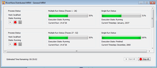
• For an iterative MRM run, it shows a single MRM run. A characteristic of iterative MRM is that the number of runs isn't known in advance, nor is the time remaining. On the simulation dialog, the labels show the current run number while the progress bar is a busy indicator, rather than showing the percent complete. The controller's user interface is:
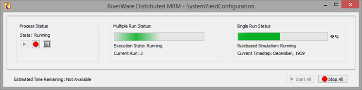
Additional information on use of iterative MRM is in “Using Iterative MRM configurations”.
For any type of simulation, if you need to interrupt a scenario while it is running, select Stop All.
Viewing Scenario Simulation Details
The Scenario List Simulator window displays detailed information for each scenario simulation.
If a scenario simulation is successful, the Run icon changes from gray to green. If a simulation is not successful, the Run icon turns red. A check mark indicates the simulation succeeded. If the check mark is orange, the simulation succeeded with a warning.
When you select a scenario, the status line displays the current status information for that scenario, including any warning messages, if applicable.
The simulation success or failure status is saved with the study and is displayed when the study is reopened.
You can manually override the Run icon color by selecting Scenarios, then Mark Checked Scenarios As Simulated or Mark Checked Scenarios As Not Simulated. For example, if a scenario simulation is successful, but the study is not saved afterward, the Run icon is gray when the study is reopened. You can correct this by manually setting the Run icon green.
If you select the File Folder icon at the end of a scenario row, a Windows Explorer window opens to the folder where the generated files for the scenario are located.
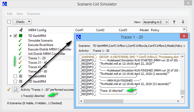
When a scenario tree view is expanded, the activities for a simulated scenario are displayed. An activity represents a step in the scenario simulation, such as initializing the model, executing the distributed MRM controller, or simulating traces. A green check mark indicates the activity was successful; a red check mark indicates the activity failed, and an orange check mark indicates the simulation succeeded with a warning. Selecting the simulation displays the warning.
Note: It is possible for the scenario Run icon to be green, even if one or more of its activities have failed.
CADSWES recommends expanding the activity lists for simulated scenarios and reviewing the activity details for any issues. When you select an activity, its status is displayed in the status area of the window. If RiverWare generated a log file for the activity, the File icon in the status message is enabled and you can select it to open the log file for viewing. This may be useful in troubleshooting issues for failed RiverWare activities. The following figure shows traces that have failed.
When a scenario simulation is run, keyword/value descriptors are created to characterize the scenario and its input events. These descriptors are written to the MRM configuration in the RiverWare distributed model as MRM descriptors. From there, they are optionally available as outputs to CSV and netCDF files from the multiple run. Descriptor keyword/value pairs are created as follows:
• Scenario name—Scenario / scenario_name
• RiverWare Policy event—Policy / event_name
• RiverWare Model event—Mode l / event_name
• RiverWare DMI event—DMI_category / event_name
• RiverWare MRM event—MRM Config / event_name
• User-created keyword/value pairs from the RiverWare MRM event window are also included.
Hiding and Deactivating Scenarios
The Scenario List Simulator window also provides options to deactivate or activate, and dynamically hide or show scenarios. These options function in the same manner as those on the Scenario List Organizer dialog box.
Deactivating a scenario makes it unavailable throughout RiverSMART and removes it from all RiverSMART dialog boxes. To deactivate scenarios, select the scenarios, and then select Edit, then Deactivate Checked Scenarios. To activate all inactive scenarios, select Edit, then Activate Inactive Scenarios.
Hiding a scenario does not deactivate it; it simply hides the scenario in the current dialog box and does not affect other dialog boxes. If many scenarios have run successfully, you may want to hide them to reduce clutter on the workspace. To hide active scenarios, select the scenarios, and then select View, then Hide Checked Scenarios. To show all active scenarios, select View, then Show Hidden Scenarios.
Study Folder Structure for Scenario Results
RiverSMART saves all scenario simulation results to the Study Folder you have specified, using the following structure.
Study_Folder\
Scenario\
scenario_name\
generated files
scenario_name\
generated files
Working\
RiverWare_event_name\
scenario_name\
log files
intermediate results
scenario_name\
log files
intermediate results
• The Scenario\ folder includes a folder for each scenario.
– Each scenario folder includes the RDF, CSV, and netCDF files generated for each scenario simulation.
• The Working\ folder includes a folder for the RiverWare event.
– The RiverWare event folder includes a folder for each scenario.
• Each scenario folder includes log files and intermediate results, which may be useful for debugging problems in event execution.
Archiving Scenarios
Scenario outputs (RDF, CSV, NetCDF, Excel, and R Script output files) can be archived as ZIP files in user-specified archive folder. Archiving is useful if you want to conserve disk space or share outputs.
To configure archiving, select Workspace, then Options from the RiverSMART menu; alternatively, select the Options button on the RiverSMART toolbar.
In the Group area of the Options dialog box, select Archiving to configure when and how to archive successful scenarios.
Note: Scenarios are not archived after errors.
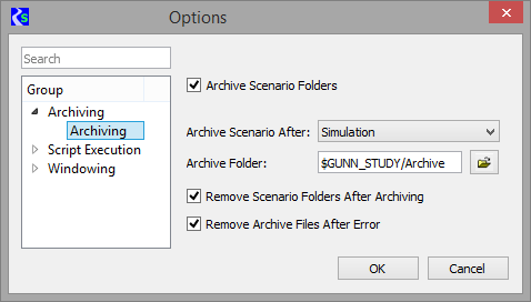
Archive Scenario Folders
Select if you want to archive scenarios. The remaining options are made available.
Clear if you do not want to archive scenarios; this is the default. The remaining options are cleared and made not available.
Archive Scenario After
Select one of the following options to specify when to archive scenarios.
• Simulation—archives after successful simulation; this is the default.
• Post-processing—archives after successful post-processing.
Archive Folder
Required field. Specify the archive folder. You can enter the path in the text box or select it through the File Chooser. The path can contain environment variables.
Remove Scenario Folders After Archiving
Select if you want scenario folders to be removed after the scenario has been archived.
Clear if you do not want scenario folders to be removed; this is the default.
Remove Archive Files After Error
Select if you want archived scenarios to be removed after an error. For example, if a scenario is simulated successfully and archived, then resimulated unsuccessfully, depending on the reasons for archiving, the archived scenario may be considered not to reflect the current state of the scenario, in which case the archive should be removed
Clear if you do not want archived scenarios to be removed after an error; this is the default.
Display Order
When scenarios are generated, simulated, or post-processed, the scenario order is determined by the order of the RiverWare inputs, with the leftmost input changing least frequently, and the rightmost input changing most frequently.
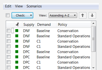
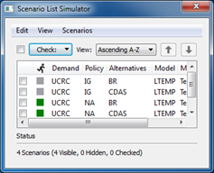
By default, scenarios are displayed in ascending alphabetical order, as shown in the following figure.
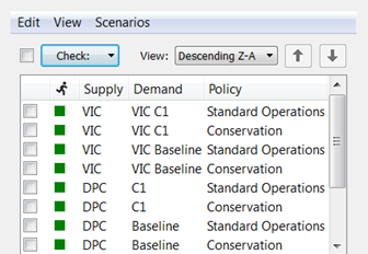
To display scenarios in descending alphabetical order, select Descending Z-A.
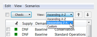
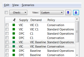
To display scenarios in a custom order, select Custom, then use the Up and Down arrows to move selected scenarios up and down one row at a time.
Updating Scenario Inputs
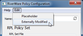
When input events (DMI, MRM, Model, or Policy) are modified, RiverSMART provides visual indicators to identify portions of the study that are out of date. If any item in an input event configuration dialog box is modified, other than the name, the event label turns red to indicate that scenarios in which the event is included must be regenerated.
If a new input event is added to the study, its label is also red, indicating that scenarios must be regenerated to incorporate the new event.
You can also manually indicate that an input event has been modified. This is useful when external files, such as a ruleset or data files, are modified, because RiverSMART is not aware of these changes. To indicate that an event has been modified, select Edit, then Externally Modified in the event configuration dialog box. This has the same effect as modifying the event configuration: the event label turns red, and RiverSMART indicates that scenarios in which the event is included must be regenerated to bring the study up to date.
As an additional indication that scenarios may be out of date, in the Scenario List Simulator and Scenario List Post-Processor dialog boxes, any scenario that includes a modified event is displayed in red text. Scenarios not affected by changes to input events remain black.
Note: In the following figure, the Run status icons are green, indicating the scenario simulations were successful. This is because the scenarios in red text have not yet been regenerated with the new inputs. The Run status is based on the most recent simulation.
To update all scenarios that have had input events modified, you must regenerate scenarios. On the RiverSMART menu, select Scenario, then Regenerate Scenarios.
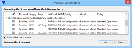
The Scenario Confirmation dialog box opens, listing the number of scenarios to be added, removed, invalidated, or unaffected, based on modifications made to input events since the last time scenarios were generated. To expand a row and list the scenarios in that category, select the arrow next to the row.
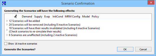
Each category description includes the number of inactive scenarios. To display inactive scenarios, select the Show inactive scenarios check box. Inactive scenarios are shown as unavailable (dimmed).
The Scenario Confirmation dialog box includes information to assist you in making informed decisions about regenerating scenarios.
Figure 2.3 Example scenario regeneration
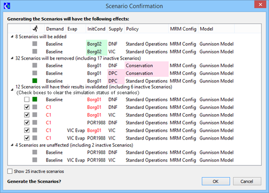
The following discussion relates to the example in Figure 2.3.
Note: Scenarios have been edited from this example to save space; therefore the counts do not match the number of scenarios shown.
In the example, pink highlights indicate scenarios to be removed, and green highlights indicate scenarios to be added. Out-of-date scenarios, whose results will be invalidated, are highlighted to indicate the input events that caused them to be out of date.
Green Run status icons identify the scenarios that have been successfully simulated. Removing these scenarios or invalidating their results could represent a loss of significant time and effort, and the simulation status informs you of this potential loss.
You can modify some input events to add scenarios without invalidating existing ones. For example, in the DMI Sequence event, extending the sequence adds scenarios without invalidating existing scenarios; however, because of the way it generates scenarios, RiverSMART cannot recognize the distinction and therefore includes the existing scenarios with the ones whose results will be invalidated.
In this example, the “InitCond” DMI sequence event was modified to add scenarios with initial condition “Borg02”. This causes scenarios with initial condition “Borg01” to be out of date. The user removed the check from the box for the “Baseline\Borg01” scenarios to preserve their results, which eliminates the need to re-simulate those scenarios. The user checks the boxes for all “C1” scenarios because they are also out of date due to the “C1” demand being modified.
When you select OK to regenerate the scenarios, all options configured in the Scenario List Organizer are reapplied; see “Generating Scenarios” for details. Once scenarios are regenerated, all event labels and scenario names in the Simulator List Simulator and Scenario List Post-Processor dialog boxes return to black. Any added scenarios and scenarios that had results invalidated by the regeneration display a gray Run status icon, indicating the scenario needs to be resimulated. Unaffected scenarios continue to display the Run status they displayed before the scenarios were regenerated.
At this point, scenarios with a gray Run status icon can be resimulated and post-processed. Scenarios with a green Run icon do not need to be resimulated because their results were not affected by the changes to the input events.
Script Execution for Notifications
After scenarios have simulated, you can execute a Windows batch script or any executable to notify you of the status. It is up to you to write the script, typically it will be a Windows Batch Script (.bat) file but can be any other executable (.exe).
To configure when and how simulation notifications are sent, select Workspace, then Options from the RiverSMART menu; alternatively, select the Options button on the RiverSMART toolbar.
In the Group area of the Options dialog box, select Script Execution.
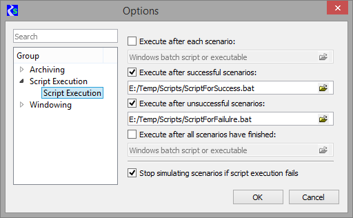
Select one or more of the following check boxes to specify when to execute the notification batch scripts.
• Execute after each scenario—execute the batch script after each scenario has simulated. The script arguments are the scenario name and status (SUCCEEDED or FAILED).
• Execute after successful scenarios—execute the batch script after each successful scenario simulation. The script arguments are the scenario name and status (SUCCEEDED).
• Execute after unsuccessful scenarios—execute the batch script after each unsuccessful scenario simulation. The script arguments are the scenario name and status (FAILED).
• Execute after all scenarios have finished—execute the batch script once after all scenarios have simulated. The script has no arguments.
If diagnostics are enabled, as described in the“Workspace Menu” section, the Diagnostics Window displays messages generated by the batch scripts. It also displays information about the execution of the batch scripts themselves, including any errors.
If you select the Stop simulating scenarios if script execution fails check box, RiverSMART will stop simulating scenarios when there is an error in the execution of a script or the script/executable finishes unsuccessfully (with a non-zero status. This option prevents situations in which simulations are failing but no notifications are sent, and you are therefore not able to intervene.
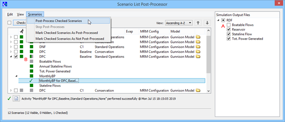
Post-processing Scenarios
The Scenario List Post-Processor dialog box displays a three-level tree view that lists the activated scenarios at the top level. Within each scenario, the events performed by post-processing are listed; and within each event, the completed activities are listed. To open this dialog box, select Scenarios, then Simulate Scenarios on the RiverSMART menu.
To initiate post-processing of scenarios, select one or more scenarios and one or more files, and then select Scenarios, then Post-Process Checked Scenarios. When a scenario is post-processed, its output files (that is, RDF or CSV) are run through the linked processes that follow each output file icon on the RiverSMART workspace. Post-processing typically involves taking an RDF file and running it through events, such as RDF Annualizer or RDF To Excel, to generate Excel workbooks that can be used for data analysis.
Files resulting from post-processing are managed by RiverSMART and are added to the Scenario\ folder of the study, in a folder with the scenario name. Log files or intermediate results are added to the Working\ folder of the study, in a folder with the event name.
If you need to halt post-processing while it is in progress, select Scenarios, then Stop Post-Processes. Post-processing of the current scenario is allowed to finish, and subsequent scenarios are not post-processed.
Viewing Post-processing Details
Figure 2.4 illustrates the following post-processing details for a scenario.
A—the Boatable Flows RDF file is not selected for post-processing.
B—the Boatable Flows RDF file was skipped when the selected scenario was post-processed; consequently, the scenario is partially post-processed, as indicated by the half-green and half-gray Post-Processing Status icon.
Figure 2.4 Scenario post-processing details
The Run icon displays the scenario simulation status: green for successful; red for unsuccessful; gray for not run.
The next column displays the Post-Processing Status icon. For a scenario, the post-processing statuses are: green for all run successfully; red for all failed; half-red and half-green for some steps successful and some failed; gray for not processed. You can manually override the Post-processing icon color by selecting Scenarios, then Mark Checked Scenarios As Post-Processed or Mark Checked Scenarios As Not Post-Processed. This is useful if the study was not saved after post-processing, causing the icons to indicate an outdated status.
If you select the File Folder icon at the end of a scenario row, a Windows Explorer window opens to the folder where the output files for the scenario are located.
When you expand a scenario tree view, additional post-processing details are displayed. The Post-processing icon displays the status of each post-processing event for the scenario.
When you select an event, its post-processing status is displayed in the status area of the window. If the event was unsuccessful, the reported error message is displayed in a second line of the status message.
If a post-processing event reports detail about its activities, the activities are listed at the next level in the tree view under the event. A green check indicates the activity was successful, and a red check indicates the activity failed.
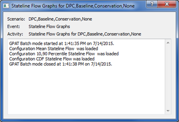
When you select an activity, its post-processing status is displayed in the status area of the window. If a log file was generated for the activity, the File icon in the status message is enabled and you can select it to open the log file for viewing. This is useful in troubleshooting issues for failed activities.
Following is a sample log file generated by GPAT Graphs for the successful Stateline Flow Graphs activity highlighted in Figure 2.4.
Hiding and Deactivating Scenarios in Post-processing
The Scenario List Post-Processor window also provides options to deactivate or activate, and dynamically hide or show scenarios. These options function in the same manner as those on the Scenario List Organizer dialog box.
Deactivating a scenario makes it unavailable throughout RiverSMART and removes it from all RiverSMART dialog boxes. To deactivate scenarios, select the scenarios, and then select Edit, then Deactivate Checked Scenarios. To activate all inactive scenarios, select Edit, then Activate Inactive Scenarios.
Hiding a scenario does not deactivate it; it simply hides the scenario in the current dialog box and does not affect other dialog boxes. If many scenarios have been successfully post-processed, you may want to hide them to reduce clutter on the workspace. To hide active scenarios, select the scenarios, and then select View, then Hide Checked Scenarios. To show all active scenarios, select View, then Show Hidden Scenarios.
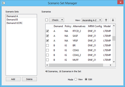
Using Scenario Sets
Scenario sets are user-defined groups of scenarios that help you to analyze and compare results across scenarios. When a study includes many scenarios, it may be impractical to include all of them on a single plot because the resulting graph would be too cluttered. Using scenario sets, you can group scenarios that you want to compare. For example, you can create a set for all scenarios that have the same hydrology but different demands and policies; or you can create a set for scenarios with a common policy but differing demands and hydrologies.
Defining Scenario Sets
The Scenario Set Manager dialog box allows you to define scenarios sets. To open this dialog box, select Scenarios, then Scenario Set Management on the RiverSMART menu.
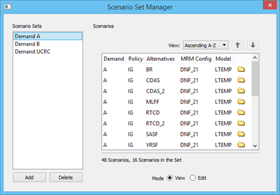
The Scenario Set Manager dialog box displays defined scenario sets. When you select a set in the Scenario Sets panel, the Scenarios panel displays the scenarios in that set. You can perform the following operations in the Scenario Sets panel.
• Add a new, empty set with a default name by selecting Add.
• Delete a selected set by selecting Delete.
• Rename a set by selecting and opening the name.
The Scenarios panel has two modes, as follows. In both modes, the scenarios are listed in the order defined in the Scenario List Simulator dialog box; see “Display Order” for details.
• View mode, shown in the previous figure, displays only the scenarios that are included in the selected scenario set. You can view and sort the scenarios, but you cannot add or remove them from the scenario set.
• Edit mode, shown in the following figure, displays all scenarios in the study. You can add or remove scenarios from a selected scenario set by selecting or clearing the scenarios using options on the Check menu.
Processing Scenario Sets
This section describes processing of scenario sets, which differs from post-processing of individual scenarios. See “Post-processing Scenarios” for details about post-processing individual scenarios.
You can configure scenario sets as input for GPAT Graphs, the R Plugin events, and the CSV Combiner. You specify the scenario sets as inputs in the event configuration; then when a scenario set is processed, the input files linked to the event are retrieved for each scenario in the set, and all are passed together to the event for processing.
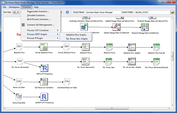
To start event processing using scenario sets, select the appropriate option on the RiverSMART Scenarios menu, as follows.
• Process GPAT Graphs—includes options for GPAT Graphs events configured to use scenario sets. The input Excel files for all scenarios in the set are passed to GPAT, which then generates the graphs. Each scenario is assigned a line in the graph, providing a visual comparison of scenario results. The graphs for each scenario set are written to an output Excel workbook, and RiverSMART adds each workbook to a folder within the ScenarioSet\ folder named for the event that generated it.
• Process R Plugin—includes options for R Plugin events configured to use scenario sets. The use of linked input files by an R Plugin is dependent on the user-created R script called by the event.
• Process CSV Combiner—includes options for CSV Combiner events configured to use scenario sets. The linked CSV files for all scenarios in the set are passed to the event, which them combines them into a single CSV output file.
Log files generated by a GPAT Graphs event, R Plugin event, or CSV Combiner event are added to the Working\ folder of the Study Folder, in a folder named for the event.
Revised: 06/04/2023