
Solution Approaches
Simulation
The Simulation Controller has the task of managing the execution of a run, including when objects solve and how they solve. As objects solve, the effects of their solutions propagate to other objects. When an object has enough information to solve, we say it is ready to dispatch.
Topics
Mathematical Basis for Reservoir Simulation
Using RiverWare requires knowledge of elementary reservoir modeling mechanics. Reservoir modeling in RiverWare is accomplished using a mass balance approach. The equation for reservoir mass balance is as follows:

For this section, it is important to more fully understand the Outflows in the above equation. Outflow in RiverWare, is expressed as follows:

Along with the greater detail in the Outflow term of the basic mass balance equation, Total Inflow in RiverWare is expressed as follows:

Further refinements may also be made to these equations and the Gain and Loss terms. Some of these include Evaporation, Precipitation, Bank Storage, Pumped Storage Flow, Seepage, Diversion, Return Flow, and Canal Flow.
Given any two of Inflow, Outflow or current Storage, the third variable may be solved for, when the previous Storage is known. Storage can also be determined from the Pool Elevation. Further, the Release (or Energy) and Spill could be specified (together) to determine Outflow.
The discretization of the values in these timeseries is important to recognize. The Inflow and Outflow slots contain the values for the average flow during each timestep, while the Storage and Pool Elevation slots contain the values at the end of each timestep. In other words, the flow values are pulse data, while the elevation and storage values are instantaneous data. Values in RiverWare slots are only as precise as the timestep length used to generate them.
Dispatch Methods
Each object in RiverWare has one or more Dispatch Methods. The Dispatch Methods represent the various combinations of inputs and outputs which are valid states for solving the object’s physical process equations. Each Dispatch Method has a list of Dispatch Conditions, a set of slots with required known values and slots with required unknown values. When the required knowns and unknowns are both satisfied, the Dispatch Method can execute. Table 1.1 lists some Dispatch Methods and their conditions for the Level Power Reservoir object.
Note: For all Dispatch Methods to be able to solve, the previous storage must also be known. This is not in the Dispatch Conditions, but is checked when the object solves.
Method | Knowns | Unknowns |
|---|---|---|
solveMB_givenInflowOutflow | Inflow Outflow | Storage Pool Elevation |
solveMB_givenInflowStorage | Inflow Storage | Pool Elevation Outflow Energy |
solveMB_givenOutflowStorage | Outflow Storage | Pool Elevation Inflow |
solveMB_givenInflowHW | Inflow Pool Elevation | Storage Outflow Energy |
solveMB_givenOutflowHW | Outflow Pool Elevation | Storage Inflow |
solveMB_givenOutflowStorage | Outflow Storage | Pool Elevation Inflow |
solveMB_givenEnergyStorage | Energy Storage | Pool Elevation Inflow |
solveMB_givenEnergyHW | Energy Pool Elevation | Storage Inflow |
solveMB_givenEnergyInflow | Energy Inflow | Pool Elevation Storage |
User Method-dependent Dispatch Methods
Dispatch Methods are registered with the controller and added to the method table at the beginning of each run. The method table contains a list of all of the potential dispatch methods for an object. Sometimes, the decision as to which Dispatch Methods to add to the method table depends on the selected User Methods. For example, the Dispatch Method listed in Table 1.2 is only added to the dispatch table when the Solve Hydrologic Inflow user method is selected.
In this case, knowing the Inflow, Outflow and Storage does not make the object overdetermined. As long as the Hydrologic Inflow is unknown, the object can dispatch the method to solve for it.
Method | Knowns | Unknowns |
|---|---|---|
solveMB_givenInflowOutflowStorage | Inflow Outflow Storage | Pool Elevation Hydrologic Inflow |
Slot Values
Slot timesteps and cells which do not have a value appear as “NaN,” or “Not a Number.” When a slot receives a value, it can occur via one of the following mechanisms:
• Direct user input
• A value propagated across a link from another object
• A value set by the object’s user or dispatch methods
Set Value
When one of the three mechanisms attempts to set a value on a slot, the following steps are taken in order:
1. Convergence. If a value already exists in the slot, check for convergence. If the difference between the old value and the new value is within the slot’s convergence criterion, do not set it. See “Configure Slot Dialog” in User Interface for details on how to set convergence for a series slot.
2. Max Iterations. If a value already exists in the slot, check max iterations. If the value has already been set as many times as the max iterations criterion, do not set it again. In this case, a warning message is posted to diagnostics. The max iterations setting is available in the Run Control dialog by selecting View, then Simulation Run Parameters from the workspace; see “Simulation Run Parameters” in User Interface for details.
3. Overdetermination. Check for over overdetermination. Overdetermination is detected by examining how the previous slot value was set. If the slot has a previous value, and this previous value was set from a different source, the object is overdetermined. In this case, post an overdetermination error and abort the run.
4. Set Value. If the previous checks succeed, set the (new) value in the slot.
5. Propagation. If the slot is linked, propagate the value across the link(s).
Object’s Response to Setting a Slot Value
When a slot is set on an object, the following occurs:
1. Dispatch Slot. Check if the slot which was set is a dispatch slot. Dispatch slots are the subset of SeriesSlots which may be Dispatch Conditions and may be linked to other objects. Only dispatch slots cause objects to redispatch when they are set. If the slot is not a dispatch slot, nothing else is done.
2. Dispatch Conditions. If the object has not yet dispatched this timestep, check the dispatch conditions of each Method on the method table. If a Method’s conditions are satisfied, this Method is used for the dispatch. If no Method’s conditions are satisfied, the object must wait for more information; nothing else is done. If the object has already dispatched this timestep, redispatch with the same Method.
3. Notify Controller. If a valid Dispatch Method was found in the previous step, notify the controller of the Method to be dispatched. The controller then puts the object on the dispatch queue.
Iteration
After an object has dispatched during a timestep, it will dispatch again if any dispatch slot is reset. When a dispatch slot’s value changes, there is a high probability that the previous solution for this object at this timestep is now invalid. Since all values are known, the object cannot match any of its Dispatch Methods’ Dispatch Conditions (remember that Dispatch Conditions include required unknowns as well as required knowns). The object redispatches using the same Dispatch Method that was invoked previously.
Simulation Controller
The Simulation Controller is responsible for maintaining the order of execution at the highest level of simulation. The steps, in order, are as follows.
1. Initialization for simulation
a. Clear all output and values from previous runs for all timesteps in all series slots.
b. Set user inputs.
c. Propagate user inputs across link.
d. Determine first dispatch timestep. See “Initialization” for details.
2. Execute rules in the Initialization Rules RPL set. See “Initialization Rules” for details.
3. Simulation Beginning of Run
a. Execute Beginning of Run methods for all objects.
b. Evaluate Beginning of run expression slots for all timesteps.
4. For each timestep:
a. Set the controller clock to the timestep time.
b. Execute Beginning of Timestep methods for all objects.
c. Evaluate Beginning of timestep, current timestep only expression slots
d. Dispatch objects until the queue is empty, simulating the effects of the user inputs and default values.
e. Execute End of Timestep methods on all objects.
f. Evaluate end of timestep, current timestep only Expression slots
5. Execute End of Run Simulation methods on all objects.
6. Evaluate End of Run expression slots.
Initialization
During Initialization of the run, the controller first resets all output slots to NaN, registers input values, and propagates values across links. Then, it finds the first dispatch timestep for each object.It then executes Initialization rules.
First Dispatch Timestep
Next, the controller determines the first timestep at which an object is allowed to dispatch. For the majority of objects, this is the start timestep. For Reaches, Control Points, and Confluences objects, it is sometimes necessary to allow dispatching to take place during prerun timesteps. This enables prerun inputs to route downstream thus allowing the system to solve on the start timestep.
Finding Earliest Upstream Inputs
For Reaches, Control Points, Confluences, Inline Power Plants, and Stream Gages, the first dispatch timestep is determined by looking for the earliest Input value on the Inflow slot (Inflow1 or Inflow2 on the Confluence). Then, the method travels upstream to the linked object (or objects in the case of a confluence) and looks for the earliest input value. This search process continues until either the top of the basin is met or a non-Reach, Control Point, Confluence, Inline Power Plant, or Stream Gage object is met.
Note: The search stops if it finds a reach with either the Kinematic, Muskingum Cunge, or MacCormack routing method selected. The first dispatch timestep is the earliest at which the object is able to dispatch; dispatching is still controlled by the object’s dispatch conditions.
Note: The search only looks for input values (“I” or “Z”) that are known before the start button is pressed. Initialization rules are executed later, so values set by those rules are not recognized as inputs.
Initialize Flow Slots for Routing
In addition to the search for earliest upstream inputs, methods in the Initialize Flow Slots for Routing category on the Computational Subbasin can be used to determine and set the number of prerun timesteps necessary for downstream lagging. See “Initialize Flow Slots for Routing” in Objects and Methods for details.
When these methods are selected, the earliest dispatch timestep is determined by also searching downstream to add up the required number of timesteps based on the selected Reach routing methods. See “Initialize Flow Slots for Routing” in Objects and Methods for details on these methods.
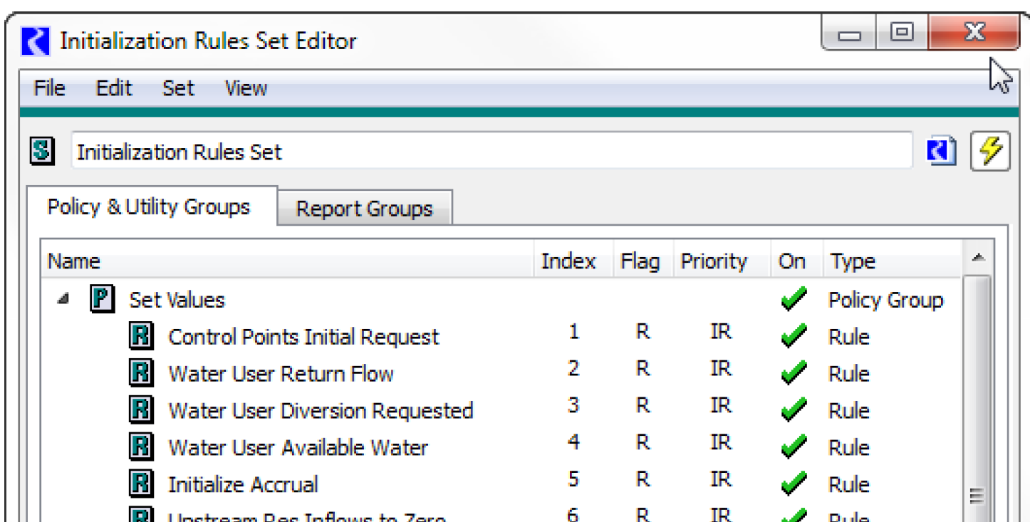
Initialization Rules
Initialization Rules are a set of RPL rules associated with the model which can be executed as part of run initialization to set up data for the run. Initialization Rules provide a complement to user inputs and execution of DMIs.
See “Initialization Rules Set” in RiverWare Policy Language (RPL) for details on Initialization Rules.
Time Horizon Simulation
Each object has its own clock. The controller clock, which is shown in the Run Status dialog, is not necessarily an indication of the timestep at which the objects are dispatching. Simulation proceeds without regard to the controller clock, except for executing the next Beginning of Timestep when the dispatch queue is empty.
Time horizon dispatching allows the system to solve over several timesteps, depending on which values are known. Due to time lags between reach Inflows and Outflows, objects may not have enough information to dispatch at a given timestep until later in the simulation. Over an entire river basin simulation, this can result in dispatching of linked objects at different timesteps.
When a model’s objects have enough information to dispatch later timesteps at the start of the simulation, they will. In such models, most of the dispatching can take place while the controller clock is still on the first timestep. In these cases, the Run Status dialog shows the controller clock on the first simulation timestep for most of the execution time. Since most of the timesteps solve, the simulation proceeds very rapidly through the other timesteps.
Note: The last timestep at which objects dispatch is typically the Finish Timestep but can be specified by the user; see “Simulation Run Parameters” in User Interface for details. This allows models that lag or forecast to correctly compute values near the end of the run.
Underdetermination
When objects do not dispatch during the run, no warning or error is generated. Lack of sufficient data to force dispatching is not considered an error. The Dispatch Information dialog should be reviewed after each run to verify that all objects dispatched for all timesteps.
Object Dispatching Patterns
Although a model may solve in many different ways, depending on its inputs and outputs, object types often dispatch in predictable ways. Several patterns of dispatching emerge from this modeling approach.
Two Reservoirs With Tailwater-dependent Energy
Two Reservoirs whose states are interdependent will alternately dispatch until they reach a stable solution. The most common example of this inter-reservoir iteration is an upstream reservoir with an Energy request whose tailwater elevation is dependent on a downstream Reservoir. The Turbine Release to meet the Energy request becomes the Inflow to the lower Reservoir. If Outflow is known, the lower Reservoir solves for a new Pool Elevation, which influences the Tailwater Elevation and Operating Head of the upstream reservoir. The iteration proceeds as follows:
1. The upstream Reservoir starts the iteration by dispatching with solveMB_givenEnergyInflow and calculating an Outflow required to meet the Energy request. This initial value is based on incomplete tailwater data. The value propagates across a link to the downstream Reservoir.
2. The upstream and downstream Reservoirs iterate with the following steps until they converge:
a. The downstream Reservoir dispatches with solveMB_givenInflowOutflow and calculates a new Storage and Pool Elevation based on the Outflow from the upstream Reservoir (Inflow) and its user-input Outflow. This Pool Elevation propagates across a link to the Tailwater Base Value of the upstream Reservoir.
b. The upstream Reservoir dispatches with solveMB_givenEnergyInflow and solves for a new Turbine Release to meet the Energy request based on the backwater effects of the downstream Reservoir (Tailwater Base Elevation) and resulting change to its Operating Head. The Outflow value propagates across a link to the downstream Reservoir.
Bidirectional Canal
The Canal object behaves differently from other objects in RiverWare. Due to instability of three object iterations, the group of objects surrounding a canal must be solved simultaneously. The order of execution is as follows.
1. One of the two Reservoirs dispatches with solveMB_givenInflowOutflow.
a. Canal Flow is linked but not known, so the Reservoir sets its current Pool Elevation to the previous timestep’s Pool Elevation and exits the dispatch.
2. The other Reservoir dispatches with solveMB_givenInflowOutflow.
a. Canal Flow is linked but not known, so the Reservoir sets its current Pool Elevation to the previous timestep’s Pool Elevation and exits the dispatch.
3. The Canal dispatches with solveFlow, which requires the following known values:
– elevation1
– elevation2
– previousElevation1
– previousElevation2
4. The Canal then solves a set of up to seven linear equations to determine the flow through the Canal. The flow value, and its inverse, are set on the flow1 and flow2 slots. These values propagate across links back to the Reservoirs.
5. Both Reservoirs redispatch independently. Since Canal Flow is linked and known, the dispatch can now solve for all of the Reservoir parameters.
See “solveFlow” in Objects and Methods for details on the canal dispatch method.
Reach and AggDiversionSite Interaction
Reach objects which are linked to an Aggregate Diversion Site also have a special dispatching order. The amount of flow in the Reach determines the quantity of water available for diversion from the Reach, and the amount actually diverted affects the quantity of Outflow from the Reach. The order of dispatching is as follows.
1. The Reach dispatches with one of two Dispatch Methods because of a known Inflow or Outflow.
a. If Inflow is known, the Dispatch Method is solveOutflow. If the Diversion slot on the Reach is linked but not known, the Available for Diversion slot is set equal to the Inflow.
b. If Outflow is known, the Dispatch Method is solveInflow. If the Diversion slot on the Reach is linked but not known, the Available for Diversion slot is set equal to the user-specified minimum Available for Diversion.
2. The Available for Diversion value propagates across the link to the Aggregate Diversion Site.
3. The Aggregate Diversion Site dispatches with processLumpedDiversion, processSequentialDiversion, or simply propagates values across links, depending on the selected Linking Structure. In all cases, a total Diversion value is determined for the Aggregate Diversion Site. This value propagates across a link to the Diversion slot on the Reach.
4. The Reach can now redispatch and solve for its Inflow or Outflow.
Revised: 11/11/2019