
Release Notes Version 2.1
This document describes new features, enhancements, and changes included in RiverWare Version 2.1, released on March 10, 1999. These changes are new to the executable since the release of RiverWare Version 2.0.3 on August 3, 1998.
Please direct questions to RiverWare Technical Support at (303) 492-0908 or support@cadswes.colorado.edu.
Required Model File Updates:
• Water User Diversion Requested and Depletion Requested no longer default to 0.0 if not input in the Input Requests Method. If one of the slots is input, RiverWare will continue to default the other slot to the input value. Models which depend on the defaults must be updated with input(s) of 0.0 to solve for the same results as prior versions of RiverWare.
• Gainloss calculations which were specific to individual Reach routing Methods are now performed in a new User Method Category called GainLoss Calculation. There are four User Methods in this new Category to cover all previous gain/loss calculations. Models saved under earlier versions of RiverWare will have slot names automatically converted to their new names, but will NOT have the appropriate GainLoss method selected. If any Reaches previously calculated gains or losses (there were non-zero values in any of the old gain/loss slots), the appropriate Method must be selected in the GainLoss Calculation Category. See “Gain Loss” for more information.
Special Attention Notes:
• When loading old models, several diagnostics messages may be generated as old slot types are automatically converted to new slot types:
• Trying to convert former slot type (“MultiSlot”) to new slot type (“SimObjMultiSlot”). Trying to convert former slot type (“SeriesSlot”) to new slot type (“AggSeriesSlot”). Do not be concerned by these messages. You do not need to make any changes to your model.
• The names of the User Methods in the Diversion from Reach and Diversion from Reservoir User Method Categories have been changed from AggDiversionSite Linked to Available Flow Based Diversion and from Diversion Object Linked to Head Based Diversion. Models which contain any of these Methods will automatically be updated upon loading.
Model Loading
“MultiSlots” renamed “SimObjMultiSlots”
All MultiSlots have been renamed SimObjMultiSlots to accommodate a software class reorganization. Additionally, some SeriesSlots have been converted to AggSeriesSlots. When loading old models, diagnostics messages may be generated as old slot types are automatically converted to new slot types:
Trying to convert former slot type (“MultiSlot”) to new slot type (“SimObjMultiSlot”).
Trying to convert former slot type (“SeriesSlot”) to new slot type (“AggSeriesSlot”).
Do not be concerned by these messages. You do not need to make any changes to your model. The use and functionality of these slots has not changed.
Simulation
Global Maximum Iterations
The maximum iterations for simulation dispatch slots is now set globally in the Simulation Controller Parameters dialog. This dialog is invoked by selecting View Controller Specific Parameters... in the Run Control dialog’s menu bar. Whereas the default maximum iterations in prior versions of RiverWare was 20, the new default for a clear workspace is 40. The maximum iterations is valid for all dispatch slots, and may no longer be set independently in each slot’s Configuration dialog.
When models saved under earlier versions of RiverWare are loaded with 2.1, the global maximum iterations value will be set to the largest maximum iterations value which was set on any of the individual slots. This ensures that maximum iterations will be large enough to allow all objects to solve as they did before.
Diversion and Return Flow Defaults
Prior to RiverWare 2.1, Reservoirs were often prevented from dispatching until the controller clock had reached the dispatch timestep. This was due to the setting of default Diversion and Return Flow (when these slots were not linked) at the beginning of each controller timestep. As a result, unknown Diversion and Return Flow values were not defaulted until the controller had executed the beginning of timestep behavior for the given timestep. Since Diversion and Return Flow are required knowns for all Reservoir dispatch methods, Reservoirs often had to wait, even though all other data was available to dispatch.
Unknown and unlinked Diversion and Return Flow slots are now set to 0.0 at the Beginning of Run. Depending on the model data, this may allow a majority of Reservoirs to go on the dispatch queue from the very first timestep. In some cases, this change may improve model run times.
Simulation Objects
Reservoir
Spillway Flashboards and Superboards
A new User Method Category, Unregulated Spill Type, has been added to Reservoir objects to model the effects of breakaway “flashboards” on unregulated spillways. The Unregulated Spill Type User Method Category is only available when a Method containing an unregulated spillway is selected in the spillCalculationCategory. There are three User Methods available for selection within this Category: the default Bare Crest Only, Flashboards, and Flashboards and Superboards.
The default Method performs no computations and existing models need not be modified. The Flashboards Method calculates Unregulated Spill based on a flashboard availability table, a flashboard spill table (for the flashboards which are up), and the unregulated spill table (for the flashboards which are down). The Flashboards and Superboards Method calculates Unregulated Spill based on the availability of flashboards and superboards (mounted on top of the flashboards), a superboard spill table (for the superboards which are up), a flashboard spill table (for the flashboards which are up), and the unregulated spill table (for the flashboards which are down). Both Methods adjust the availability of flashboards and superboards at each timestep based on user-input flashboard and superboard failure elevations. Due to drastic changes in spill volume when boards fail, the failure time of boards is calculated and modeled at a finer time resolution than the model run timestep. Detailed documentation of the two Methods may be found in the Simulation Objects Online Documentation.
Uncertainty Calculation
A new User Method Category, Uncertainty Calculation, has been added to Storage Reservoir and Level Power Reservoir objects. There are two User Methods available for selection within this Category: the default No Uncertainty, and FOSM Uncertainty.
The default Method performs no computations and existing models need not be modified. The FOSM Uncertainty Method is first-order second-moment approximation for modeling system uncertainties. The uncertainty computations are executed at the end of the dispatch routines for all dispatch methods which do not have Energy or Spill as input slots. The slots for which uncertainties may be specified are Inflow, Outflow, Storage, Pool Elevation, Hydrologic Inflow, Evaporation, and Bank Storage. Detailed documentation of this Method may be found in the Simulation Objects Online Documentation.
Reach
Gain Loss
Gainloss calculations which were specific to individual routing Methods in earlier versions of RiverWare are now available to all routing Methods. A new User Method Category called GainLoss Calculation, has been added to Reach objects. There are four User Methods available for selection within this Category: the default No GainLoss, Constant GainLoss, Variable GainLoss, and Seasonal GainLoss Flow Table. The default method performs no computations. Detailed documentation of the three other Methods may be found in the Simulation Objects On-line Documentation.
Models saved under earlier versions of RiverWare will have slot names automatically converted to their new names, but will NOT have the appropriate GainLoss method selected. If any Reaches previously calculated gains or losses (there were non-zero values in any of the old gain/loss slots), the appropriate Method must be selected in the GainLoss Calculation Category.
Old Slot Name | New Slot Name | |
|---|---|---|
Constant GainLoss | -> | GainLoss |
GainLoss Coefficient | -> | GainLoss Coefficient (no change) |
Constant GainLoss Coefficient Interpolated | -> | Variable GainLoss |
Variable GainLoss Coefficient Interpolated | -> | Variable GainLoss Coeff |
Constant GainLoss Coefficients | -> | Variable GainLoss Table |
Variable GainLoss Coefficients | -> | Variable GainLoss Coeff Table |
Constant Loss | -> | Variable GainLoss (SIGN CHANGE: positive value is now a gain) |
Fractional Loss | -> | Variable GainLoss Coeff (SIGN CHANGE: positive value is now a gain) |
Variable Lag Time Interpolated | -> | Variable Lag Time |
Variable Lag Times | -> | Variable Lag Time Table |
If a model was previously using the Constant GainLoss slot to compute reach loss, the data within this slot will be automatically converted to the new slot (GainLoss) but the user must select Constant GainLoss within the GainLoss Calculation category for the new slot to be active.
If a model was previously calculating gains or losses in a routing Method which used only the Variable GainLoss Coefficients and Variable GainLoss Coefficient Interpolated slots (Muskingum Cunge, Kinematic Routing, or MacCormack Routing), the Seasonal GainLoss Flow Table method must be selected. The data within the slots will be automatically transferred to Variable GainLoss Coeff Table and Variable GainLoss Coeff, however the Variable GainLoss Table will also be added. This table must contain values for the simulation to run. The table can be filled with zeros for the simulation to run identical to the previous model.
If the user was using either the Variable Muskingum or Muskingum Cunge routing methods, and Previous Flow Average was selected in the Apply Fractional Loss User Method Category, the following changes must be made: The proper Method must be selected in the GainLoss Calculation Category since the Fractional Loss Category no longer exists and Previous Flow Average must be selected in the Apply GainLoss Category. This Method works exactly the same as the previous method, however, it will not be selected by default because the name of the Method Category has changed.
“ssarrRouting” renamed “Storage Routing”
The ssarr User Method in the routingMethodCategory User Method Category of Reach objects has been renamed Storage Routing. There is no functional difference between the two User Methods. Models saved under earlier versions of RiverWare will have the Method name changed automatically and will solve the same way as they did before.
Variable Storage Routing
A new User Method, Variable Storage Routing, has been added to the routingMethodCategory of Reach objects. This routing Method is identical to the Storage Routing Method except that its storage time exponent and storage time coefficient vary over time rather than being constant values. The exponent and coefficient are determined at each timestep from a table lookup given the flow at that timestep. Detailed documentation of this Method may be found in the Simulation Objects Online Documentation.
Contingent Local Inflow
A new User Method, contingentLocalInflow, has been added to the localInflowCalculationCategory of Reach objects. The contingentLocalInflow User Method Category is only available when noRouting is selected as the routingMethodCategory. This local inflow Method changes the way in which the Reach solves depending on the known slots. If Local Inflow is known, it is used with the other known slot (Inflow or Outflow) to solve for the unknown (Outflow or Inflow). If Local Inflow is not known and only one of Inflow or Outflow is known, Local Inflow is set to 0.0 and the unknown slot is solved for. If Local Inflow is not known but both Inflow and Outflow are, Local Inflow is solved for. Detailed documentation of this Method may be found in the Simulation Objects Online Documentation.
Knowns | Assumption | Solve For |
|---|---|---|
Inflow, Local Inflow | none | Outflow |
Outflow, Local Inflow | none | Inflow |
Inflow | Local Inflow = 0.0 | Outflow |
Outflow | Local Inflow = 0.0 | Inflow |
Inflow, Outflow | none | Local Inflow |
Seepage
A new User Method Category, Seepage Calc, has been added to Reach objects to model losses into groundwater. The Seepage Calc User Method Category is only available when noRouting is selected as the routingMethodCategory. This alleviates any confusion as to whether the seepage loss is applied before or after routing. There are three User Methods available for selection within this Category: the default No Seepage, Proportional Seepage, and Variable Seepage.
The default Method performs no computations. The Proportional Seepage Method calculates Seepage using a single Seepage Flow Fraction. The Variable Seepage Method calculates Seepage using a timeseries of Variable Seepage Flow Fractions. Seepage losses are applied at the top of a Reach, prior to any diversion, return flow, and/or gainloss.The calculated Seepage slot may be linked to a GroundWater Storage object. Detailed documentation of the two Methods may be found in the Simulation Objects Online Documentation.
Time Lag Routing Upstream
The timeLagRouting Method has been enhanced to allow solving for Inflow based solely on Outflows. In prior releases of RiverWare, at least one Inflow was required for this Method to solve upstream. It will now dispatch and solve with Outflow only.
Distribution Canal
Request Routing
A new User Method, No Routing, has been added to the Request Routing Category of Aggregate Distribution Canal objects. The new Method allows a Distribution Canal network to be modeled in a non-request routing mode. In this mode, the Inflow into the top portion of the Canal system must be set in a different way (user input, linked from a Diversion Object, or return flow from another Canal or a Water User). The advantage to this Method, is the ability to operate a Canal system from the top down, rather than the bottom up (supply-driven rather than demand-driven). The new No Routing Method is the default Method for the Request Routing Category and performs no computations. Detailed documentation of this Method may be found in the Simulation Objects Online Documentation.
Flow Routing
Three new User Methods have been added to the Flow Routing Category of Distribution Canal element objects. These User Methods are only available when No Routing is selected as the Request Routing Method in the Aggregate Distribution Canal object. In this case, the canal system is being operated in a top-down manner. This allows additional flexibility in routing algorithms because they only need to solve downstream. The three new Flow Routing Methods are the default No Routing, Storage Time, and Variable Storage Time.
The default Method performs no routing computations. The Storage Time Method is similar to the Storage Routing Method of Reach objects. The Variable Storage Time Method is similar to the Variable Storage Routing Method of Reach objects. Detailed documentation of these Methods may be found in the Simulation Objects Online Documentation.
Canal Seepage
A new User Method Category, Canal Seepage, has been added to Distribution Canal element objects to model losses into groundwater. There are three User Methods available for selection within this Category: the default None, Seepage Calc, and Variable Seepage Calc.
The default Method performs no computations. The Seepage Calc Method calculates Canal Seepage using a single Seepage Flow Fraction and a Maximum Seepage. The Variable Seepage Calc Method calculates Canal Seepage using a timeseries of Variable Seepage Flow Fractions and a Maximum Seepage. In both cases, the seepage is subtracted from the canal’s flow before any routing is done. The calculated Canal Seepage slot may be linked to a GroundWater Storage object. Detailed documentation of these Methods may be found in the Simulation Objects Online Documentation.
Canal Maximum Capacity
A new User Method Category, Canal Maximum Capacity, has been added to Distribution Canal element objects to model surface overflow at canal structures. There are two User Methods available for selection within this Category: the default None, and Maximum Capacity.
The default Method performs no computations. The Maximum Capacity Method calculates Canal Spillover as any portion of the canal element Inflow which is greater than the Maximum Capacity. The calculated Canal Spillover slot may be linked to a lateral Distribution Canal’s Inflow, or a Reach or Reservoir’s local Inflow. Detailed documentation of the two Methods may be found in the Simulation Objects Online Documentation.
Stream Gage
Internal Link
The Stream Gage object no longer dispatches. Instead, flow values propagate across a link between the Inflow and Outflow slots. The link is automatically created when the Stream Gage is pulled off of the palette. Older models which contain Stream Gage objects will automatically be updated to include the link when the model is loaded.
Groundwater Storage
Excess GW Storage
A new User Method Category, called Excess GW Storage, has been added to Groundwater Storage objects to model groundwater saturation. The Method determines what to do with groundwater which is beyond the limits of the maximum groundwater capacity. There are three User Methods available for selection within this Category: the default No Excess Storage, Excess Storage to Outflow, and Excess Storage Divert.
The default Method performs no computations. The Excess Storage to Outflow Method adds any end-of-timestep storage greater than the Max GW Capacity to the Outflow slot. This simulates a situation where a full aquifer “spills” in the normal downgradient direction. The Excess Storage Divert Method allocates any end-of-timestep storage greater than the Max GW Capacity to the linkable Excess GW Outflow slot. This simulates a situation where a full aquifer “spills” by recharging another object such as a river or reservoir. Excess storage is determined only after the mass balance with Inflow, Deep Percolation, and Outflow has been calculated. Detailed documentation of the two Methods may be found in the Simulation Objects Online Documentation.
Deep Percolation
A new User Method Category, called GW Deep Percolation, has been added to Groundwater Storage objects to model the vertical movement of groundwater into deeper aquifers. The Method calculates a vertical seepage using similar algorithms to the horizontal outflow calculation. There are four User Methods available for selection within this Category: the default No Percolation, Input Percolation, Linear Percolation, and Exponential Percolation. The default Method performs no computations and existing model files need not be modified.
In low Storage situations, deep percolation is the preferred mechanism of Storage loss. If there is not enough Storage to satisfy Pumping Calc pumping requests, GWOutflowCalc outflow requirements, and GW Deep Percolation percolation requirements, the calculated values of the Methods are shorted in the order just listed. Detailed documentation of the three Methods may be found in the Simulation Objects Online Documentation.
Pumping Calc
A new User Method Category, called Pumping Calc, has been added to Groundwater Storage objects to allow pumping of groundwater by Water User objects. The Method calculates a maximum Available for Pumping value and lets the Water User object determine the amount of Pumped Flow. There are two User Methods available for selection within this Category: the default No Pumping, and Input Pumping. The default Method performs no computations and existing model files need not be modified.
The Input Pumping Method calculates Available for Pumping at the next timestep based on the end of timestep Storage and the projected Outflow and Percolation at the next timestep, such that Storage is never allowed to become negative. The Available for Pumping propagates across a link to a Water User object which determines the amount to pump and propagates this value back to the Pumped Flow slot. Detailed documentation of this Method may be found in the Simulation Objects Online Documentation.
GW Alpha Param
The GW Alpha Param slot, which is used by the LinearFlow and ExponentialFlow Methods of the GWOutflowCalc Category has been changed. The units for this slot are now in “per time” [1/t]. This is the correct unit type for this slot, given the algorithm it is used in. Old models which contain this slot should be modified. The only way to change the slot units is to delete the object from the model, then pull a new object from the object Palette. Models which are not modified will continue to solve in the same way they did before, but the potential for confusion in the use of this slot will continue to be great.
Water User
“Stand Alone” Water User Object
The Water User object, which was previously available only as a member of an Aggregate Diversion Site, is now available as a “stand-alone.” The new object is created by dragging its icon off of the object Palette onto the workspace. The new Water User object contains all of the User Method Categories and User Methods which are available for Water User elements of Aggregate Diversion Sites linked with the noStructure Link Structure. Individual Water Users linked to a Diversion Object provide similar modeling capabilities to an Aggregate Diversion Site with considerably more flexibility.
Water User Conjunctive Use
A new User Method Category called Conjunctive Use, has been added to Water User objects. There are two User Methods available for selection within this Category: the default No Conjunctive Use and Supplement Diversion. The default method performs no computations. Models saved under earlier versions of RiverWare do not require any modifications and will solve the same way as they did before.
The new Supplement Diversion Method pumps water from a Groundwater Storage object to supplement surface water deliveries in time of shortage. The allocation of pumped water is contingent on pumping availability and may be allocated to Water Users in an Aggregate Diversion Site in accordance with their groundwater rights priorities. This Method Category is also available to Aggregate Diversion Sites using the lumpedStructure Link Structure. Complete documentation for this Method and Category are available in the Simulation Objects Online Documentation.
Diversion Object
Available Flow Diversion
A new User Method, Available Flow Diversion, has been added to the Available Flow Calculation Category of Diversion Objects. This Method allows a Diversion Object to divert water from a Reservoir or Reach based on the water available for diversion from that object, rather than the objects elevation or stage. This flow-based diversion (as opposed to a head-based diversion) nearly replicates the behavior of the Aggregate Diversion Site. The diverted amount is calculated as the lesser of the Diversion Request, Available For Diversion, and Max Diversion. A Min Diversion, the smallest diversion possible, is also specified. Detailed documentation of this Method may be found in the Simulation Objects Online Documentation.
Rulebased Simulation
Iteration Checking
The efficiency of slot iteration checking has been greatly improved. Iteration checking occurs when the Check Iterations box is selected in the Controller Parameters dialog. Checking is now done only for dispatching slots and only at the current controller timestep. This improvement can result in run time savings of up to 15% on some models where slot iteration checking is turned on.
STRING == and !=
Equality (==) and inequality (!=) comparisons of STRING expression types are now permitted within rule expressions. The comparisons evaluate to the BOOLEAN expression types TRUE or FALSE. Comparison is exact and case-sensitive.
GetObjectsInBasin() renamed ListSubbasin()
The GetObjectsInBasin() predefined function has been renamed ListSubbasin(). Rulesets with the old name will continue to work, but only the new name appears in the predefined function selector. There is no computational difference between the two functions.
Predefined Functions
Many predefined functions have been added to the Rulebased Simulation Palette. The new functions, as well as all of the existing functions, are currently being documented. This document will soon be available online. Meanwhile, contact RiverWare Technical Support if you have any questions about specific functions in the Palette.
GUI (Graphical User Interface)
Diversion Object Icon
The Diversion Object Icon has been changed from the image at left to the image at right. This is only a cosmetic change.
Subbasins
New Subbasin Manager
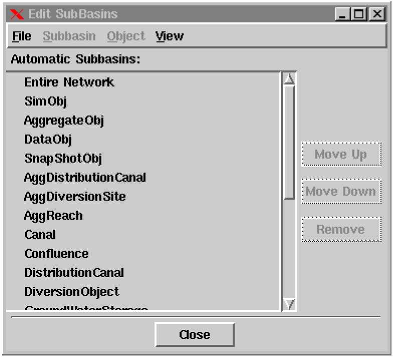
The Subbasin Manager has been completely redesigned to facilitate growing needs, but no changes to existing models are necessary. The Subbasin Manager, invoked by selecting Workspace Edit SubBasins... from the main RiverWare menu bar, now has two views, User-Defined SubBasins and Automatic SubBasins. The views are selected in the SubBasin Manager’s View menu. The default view is the automatic subbasins view shown below:
Automatic subbasins are generated by RiverWare and may not be renamed or reordered, or have their members modified or reordered. User-defined subbasins are defined by the user and saved in the model file. They may be renamed and reordered, and their member objects may be modified and reordered. A sample user-defined subbasin view is shown below:
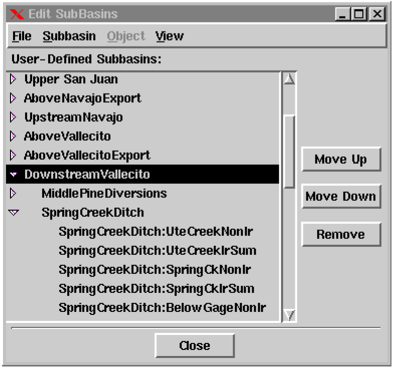
The triangles to the left of each subbasin are used to open (and close) the list of member objects in that subbasin. Member objects are indented one level. The triangles to the left of aggregate member objects are used to open (and close) the list of element objects. Element objects are indented one additional level from their aggregate “parent” object.
Subbasin names are modified by clicking on their existing name and typing a new name into the resulting textfield. The other commands available are:
Subbasin Delete Subbasin Deletes the currently highlighted subbasin.
Subbasin Insert New Subbasin Before Creates a new subbasin, which includes any objects currently highlighted on the workspace, and inserts it before the currently highlighted subbasin.
Subbasin Append New Subbasin Creates a new subbasin, which includes any objects currently highlighted on the workspace, and appends it to the end of the subbasin list.
Subbasin Invoke Member Selector Brings up an object selector dialog and adds any selected objects to the currently highlighted subbasin’s membership.
Subbasin Replace Members from Workspace Removes the selected subbasin’s members and replaces them with any objects currently highlighted on the workspace.
Subbasin Append Members from Workspace Retains the selected subbasin’s members and adds to them any objects currently highlighted on the workspace.
Subbasin Select Members on Workspace Highlights the selected subbasin’s members on the workspace.
Object List Subbasin Membership Brings up a dialog with a list of the subbasins to which the highlighted object belongs.
Object Select Object on Workspace Highlights the selected object on the workspace.
Move Up Moves the currently highlighted subbasin or member object up one level.
Move Down Moves the currently highlighted subbasin or member object down one level.
Remove Deletes the currently highlighted subbasin or member object.
SCT (System Control Table)
Shaded Rules Flag Values
Slot values which have an R (Rule) flag are now shaded light green in the SCT. This flag information was previously available only in the open slot dialog and Model Run Analysis dialog. The new shading appears in the SCT legend as shown below:

All of the shading possibilities are now:
• O = Output (any series slot)
• I =Input (any series slot)
• B=Best Efficiency (Energy slot)
• M=Max Capacity (Energy and Outflow slots)
• D=Drift (Regulated Spill and Bypass slots)
• R=Rule (any series slot)
Unlike the other flags, the Rule flag may not be set directly by the user.
Outlined Target Ranges
All target ranges are now outlined in the SCT. The outline is drawn from each tb or TB flag (Target Begin) to the corresponding T flag (Target) on Storage and Pool Elevation slots. Prior versions of RiverWare only outlined target ranges which began with an explicit TB flag. While we still recommend that you mark the beginnings of target ranges with explicit TB flags, there are situations in which this may not be possible.
RCL (RiverWare Command Language)
Model File to Load
RiverWare may now take a command line argument to indicate a model file to load upon starting. The executable comes up in the normal interactive mode, but immediately begins loading the specified model file. The syntax is:
riverware --file <model file>
Diagnostics
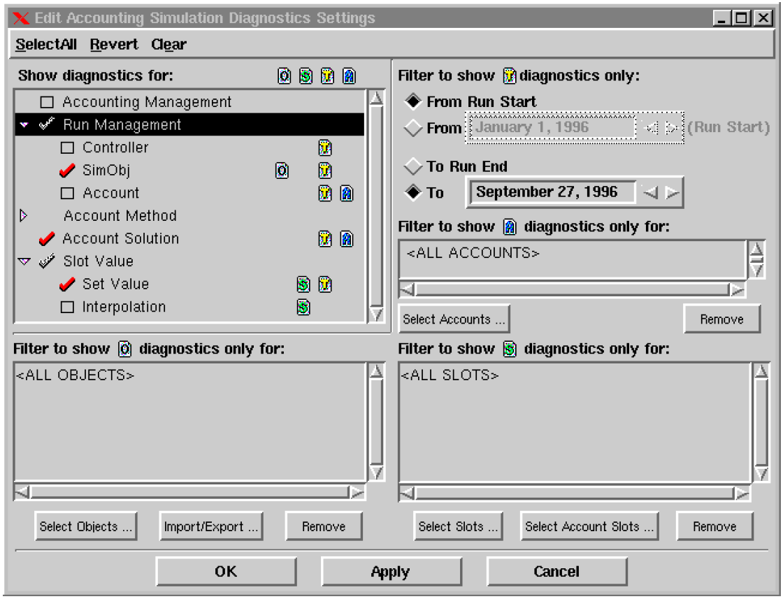
Accounting Diagnostics
A diagnostics settings dialog has been added to allow generation and filtering of Accounting run information in the same way as Simulation, Rulebased Simulation, and Optimization. The dialog is invoked by clicking on the Accounting button in the Diagnostics Manager:
Closed Bug Reports
The following is a list of the bugs which were fixed for this release. If you wish to view the details for a specific bug, please browse to http://cadswes.colorado.edu/users/gnats-query.html and search our bug database. You will need a RiverWare user login and password.
665 | 731 | 901 | 944 | 945 | 1027 | 1030 |
1035 | 1152 | 1273 | 1339 | 1342 | 1371 | 1466 |
1471 | 1552 | 1664 | 1692 | 1695 | 1699 | 1713 |
1798 | 1812 | 1836 | 1842 | 1847 | 1848 | 1851 |
1857 | 1863 | 1888 | 1891 | 1904 | 1913 | 1914 |
1920 | 1923 | 1924 | 1930 | 1931 | 1938 | 1940 |
1943 | 1945 | 1947 | 1948 | 1949 | 1950 | 1951 |
1952 | 1953 | 1954 | 1955 | 1956 | 1957 | 1959 |
1960 | 1961 | 1962 | 1964 | 1965 | 1967 | 1970 |
1972 | 1974 | 1975 | 1981 | 1986 | 1988 | 1989 |
1991 | 1994 | 1995 | 1996 | 1997 | 1999 | 2000 |
2003 | 2004 | 2007 | 2008 | 2010 | 2013 | 2014 |
2016 | 2030 | 2034 | 2035 | 2037 | 2038 | 2040 |
2041 | 2045 | 2046 | 2051 | 2052 | 2053 | 2055 |
2060 | 2064 | 2065 | 2066 | 2068 | 2069 | 2073 |
2076 | 2078 | 2079 | 2080 | 2085 | 2086 | 2088 |
2091 | 2092 | 2093 | 2097 | 2098 | 2107 | 2110 |
2111 | 2112 | 2113 | 2114 | 2116 | 2119 | 2120 |
2121 | 2122 | 2124 | 2131 | 2133 | 2134 | 2135 |
2136 | 2140 | 2149 | 2150 | 2151 | 2155 | 2159 |
2160 | 2163 |
Revised: 11/11/2019