
Routing Holdouts
This section describes a modeling technique to route the “Holdouts” or the water that was held back by a particular reservoir that would have otherwise flowed downstream. This holdout is computed using observed data:
Holdout = Max(Reservoir Observed Inflow - Reservoir Observed Outflow, 0cfs)
This holdout is computed for each reservoir individually but is then distributed to each downstream Control Point according to the intervening reaches and selected routing methods. This allows the USACE to report for each Control Point how much flow is avoided (i.e. the holdout) for each upstream reservoir, giving a good indication of the benefits provide by each reservoir. The reservoir holdout and control point routed holdout becomes an input to the benefits calculation.
The general process to compute this is as follows and repeated for each reservoir:
1. Set all local inflows and headwater inflows to zero
2. For a particular reservoir, set the inflow or hydrologic (i.e. the local) inflows to the holdout for that reservoir
3. With all reservoirs still passing flows, solve the system for the time range, routing the holdouts downstream.
4. Once that run is finished, for each downstream control point, preserve the outflow as the flow holdout for that reservoir.
5. Return to step 1. and repeat for the next reservoir.
6. Once all the runs are completed for each reservoir, run a DMI to output all reservoir and control point holdouts to the database.
This remainder of this section describes one approach to route the holdouts from each reservoir individually to get the routed holdout at each Control Point. First we will describe all of the pieces, utilities and components of this approach. Then we will describe how they all work together using iterative MRM.
Modeling Components
This section describes all of the pieces, utilities and components of this approach.
Subbasins
The following Subbasins or collection of objects are needed:
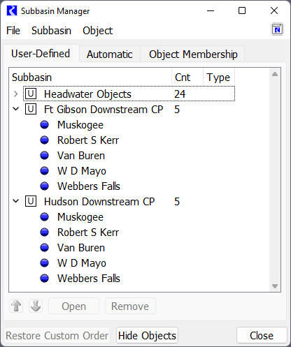
• Headwater Objects – all objects at the top of the network where the Inflows should be set to zero.
• Reservoir Downstream CP – There needs to be one subbasin for each reservoir. The contents of the subbasin is the set of downstream Control Points that receive the flow.
The following image shows the Subbasin manager with three subbasins: Headwater Objects along with two Reservoir Downstream CP subbasins, one for Ft Gibson and one for Hudson. Note, these are tandem reservoirs so they both contain the same downstream Control points.
Two other subbasins may be useful for working with objects:
• Reservoir Data Objects
• Control Point Data Objects
These subbasins contain the respective data objects and can be used when manipulating slots or looking for a particular set of data objects
Custom Slots
In the sample model, there is one data object associated with each reservoir and control point.
Tip: This process could be simplified by placing the custom slots directly on the Control Points or Reservoirs. The modelers working with the sample model preferred to add custom slots to the associated data object.
The following slots should be added:
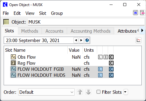
• On each Control Point Data Object: one series slot for each upstream reservoir with the naming convention: FLOW HOLDOUT RES. For example, the MUSK data object has slots for FLOW HOLDOUT FGIB and FLOW HOLDOUT HUDS.
• On each Reservoir Data Object: one series slot for the reservoir with the name: FLOW HOLDOUT.
• The reservoir data object in the sample model also contains the slots used to compute the hold out: ResOut and ResIn.
These slots should have unit type of FLOW. Use the copy/paste or Copy Slots to Objects functionality to quickly duplicate a slot to many objects. A sample of the two slots on MUSK is shown in the screenshot:
Object Attributes to define Object relationships
In the sample model there is one data object associated with each reservoir and control point. These data objects do not follow a naming convention. As a result, methodology using Object Attributes was developed to associate the two object together.
Tip: If the slots described above were placed directly on the Control Points or Reservoirs, these object attributes and RPL logic would not be necessary. All script, RPL logic and DMIs would refer to the simulation object and not the data object.
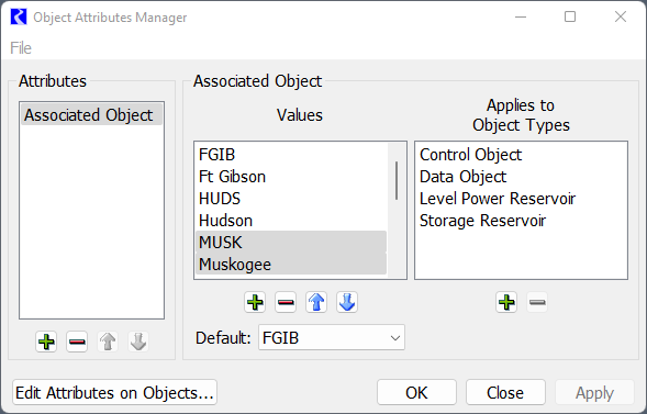
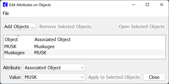
In the Attribute Manager, an attribute “Associated Object” is defined. Values for each Control Point, Reservoir and Data Object are then defined with the Name as the Value. The following screenshot shows the Attribute and Values for FGIB, Ft Gibson, HUDS, Hudson, MUSK, and Muskogee.
On each object, the value for the Associated Object should then be selected. That is, for the MUSK data object, the Muskogee attribute should be select. For Muskogee, the MUSK attribute should be selected. The following screenshot shows this example:
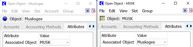
Select these on each Open Object or use the Edit Attributes on Objects tool.
Iteration Data Object
A single data object named Iteration Data defines the slots used in the iteration scheme:
• Reservoir Control List: This table slot has one row per reservoir. The row labels must match the reservoir object name exactly. The values in the cells indicate if that reservoir should be considered and allows the order of reservoirs to be defined. See the description on the slot for information on specifying the order.
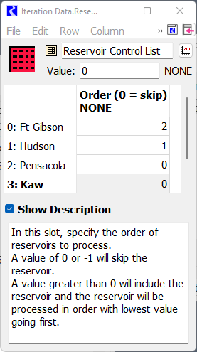
In the screenshot, Pensacola and Kaw are disabled and will be skipped (value is 0). Hudson will go first (value is 1) and then Ft Gibson (value is 2). The actual numbers don’t matter, just their relative ordering.
• Reservoir Index – This output Integer Indexed Series slot is the index of the reservoirs in the above table after removing reservoirs to skip and sorting. This is the computed slot used by the iterative MRM that controls when each reservoir is considered.
Scripts
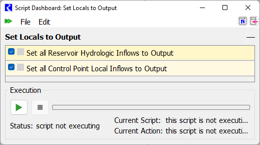
One script is required to set values to output so that they will be cleared in the next run. The Set Locals to Output script has two Set Series Slot Flags actions:
• Set all Reservoir Hydrologic Inflows to Output
• Set all Control Point Local Inflows to Output
A screenshot of the script is shown:
The slot selections for these two actions use wild cards so if reservoirs or control points are added, no changes need to be made.
Iterative MRM Rules Set
The Iterative MRM Rules Set defines the logic that will be executed before each run and after each run. A screenshot of the ruleset is shown:
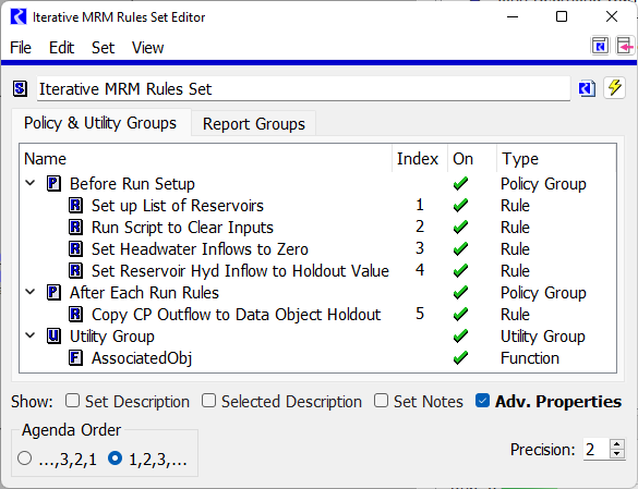
We will note that the Agenda Order is set to 1,2,3... as that makes the most sense for MRM rules. Each rule is only executed once. There are 5 rules in this set in two groups. The following screenshots show the logic in case the sample model is not available.
Figure 4.3 Rule1 sets up the list of reservoirs
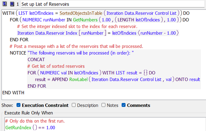
Figure 4.4 Rule 2 executes a script to set values to ouput
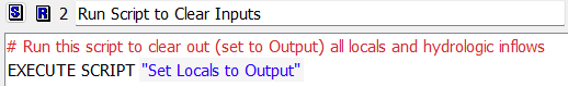
Figure 4.5 Rule 3 sets all headwater inflows to zero
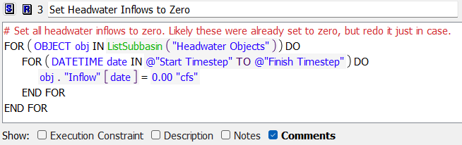
Figure 4.6 Rule 4 sets inflow or hydrologic inflow to the holdout value
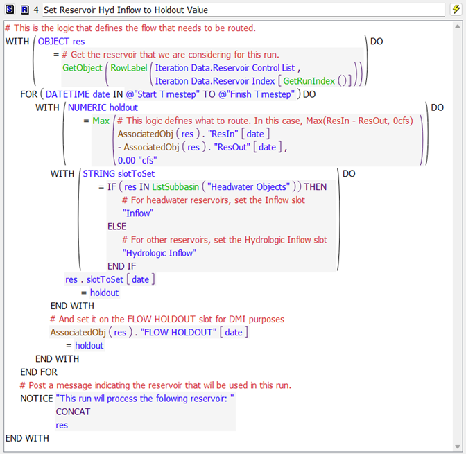
Rule 4 has stop on NaN set to stop the run if there are missing values. With this parameter set, an error will be posted if a NaN is encountered. The message will say the slot and the timestep at which the NaN is found.
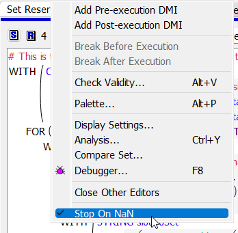
Figure 4.7 Rule 5 is a post-run rule and copies the resulting control point outflow to the data object as the Routed Holdout
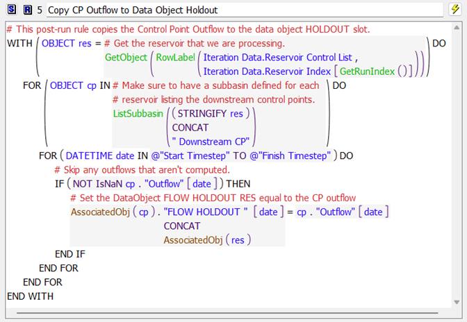
Figure 4.8 This function gets the associated data or simulation object using object attributes
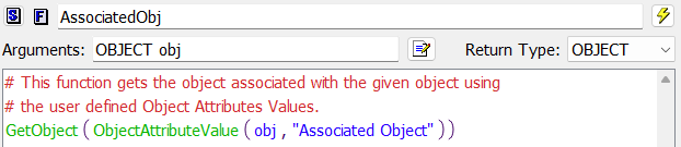
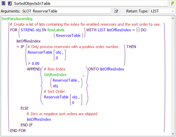
Figure 4.9 This function gets the sorted list of reservoirs to process
Iterative MRM Configuration
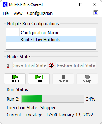
The iterative MRM configuration brings everything together to make the runs. Here, we have created a configuration called Route Flow Holdouts:
Double click the Route Flow Holdouts to open it and switch to the Iterative Runs tab:
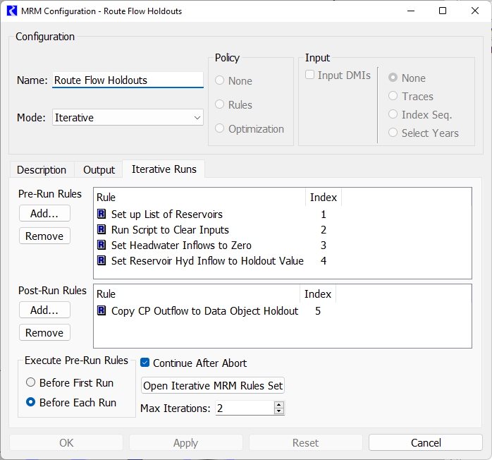
There are a few key parts to this that we will describe:
• Name: Route Flow Holdouts. Change this as desired.
• Mode: Iterative. This must remain Iterative.
• Pre-Run Rules: Make sure rules 1-4 are displayed.
• Post-Run Rules: Only MRM rule 5 is selected.
• Execute Pre-Run Rules: Must remain as Before Each Run as we want to execute rules 1-4 before each reservoir is processed.
• Continue After Abort: You can change this if needed.
• Max Iterations: This is important. Set this value to the number of runs you would like to make. This setting along with the Iteration Data.Reservoir Control List specify how many runs and which reservoir are considered.
Warning: Max Iterations must be set to the desired number of runs. Set it too high and it will make extra runs or error. Set it too low and some reservoirs will not be considered.
Database DMI and Name map
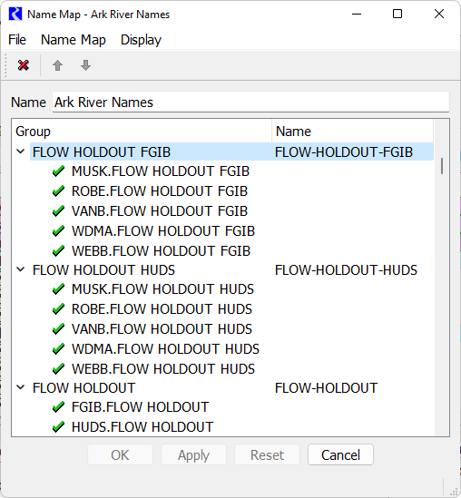
To send the resulting data out to DSS files, a Database DMI and a Name Map are required. We will not cover that here, except to note that the slots created in this sample basin are on the data object. A name map is required if the part information does not match the slot names. Here, we have slot names RES.FLOW HOLDOUT and CP.FLOW HOLDOUT RES while the names in the DSS file have hyphens: FLOW-HOLDOUT and FLOW-HOLDOUT-RES. Unfortunately slot names in RiverWare cannot contain hyphens or we could have changed the slot names to match the DSS file path names. As a result we created the following Name Map to do that translation.
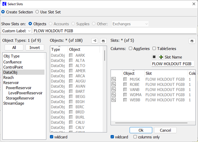
The three items are Slot Selections, (not object selections). Double clicking the first one for FLOW HOLDOUT FGIB gives the slot selector. This shows how we used wildcards and filters to create and name (using Custom Label) the selection to be FLOW HOLDOUT FGIB.
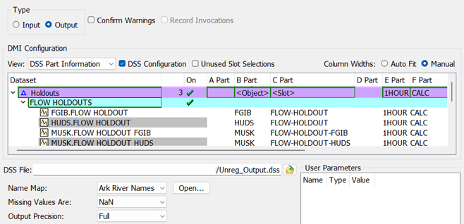
This name map can then be used by any Database DMI or Dataset that is used to output these slots. Below is a screenshot of part of a DMI that will send out the FGIB, HUDS, and MUSK holdout slots:
How it all Works
With all of the components described above, we will now describe how all of these pieces work together, with many references to the sections above.
When you select start on the MRM run controller with the “Route Flow Holdout” configuration selected (Iterative MRM Configuration), it does the following:
1. On the first run, MRM rule 1 (Figure 4.3) sets up a list of the reservoirs to process. The list filters out any reservoirs that are specified to be skipped and then is sorted by the user specified order. The reservoir index is written to the Iteration Data.Reservoir Index slot, one reservoir per row where each row represents one run to make.
2. Then MRM rule 2 (Figure 4.4) executes the “Set Locals to Output” script (Scripts). This changes the flag of all local and hydrologic inflows to output. These output values are cleared at the start of each run.
3. MRM rule 3 “Set Headwater Inflows to Zero” (Figure 4.5) then sets Inflows slots on objects in the “Headwater Objects” subbasin (Subbasins) to zero for all timesteps.
4. MRM rule 4 “Set Reservoir Hyd Inflow to Holdout Value” (Figure 4.6) then sets the reservoir hydrologic (i.e. the local) inflows to the holdout value for the reservoir under consideration for this run. It does this for all timesteps in the run.
5. Now, the individual run proceeds. With all the reservoirs passing flows, the system solves for the run range, with reaches routing the holdouts downstream. Because all other inflows are zero, only the holdouts get routed.
6. Once the individual run is finished, the post-run MRM rule 5 “Copy CP Outflow to Data Object Holdout” (Figure 4.7) loops over each downstream control point (using the reservoir’s Downstream CP subbasin), and writes the Control Point.Outflow to the flow holdout slot for that reservoir, FLOW HOLDOUT RES (Custom Slots).
7. Return to step 2. and repeat through step 6. When finished with all reservoirs or the MRM max iterations is met (Iterative MRM Configuration), the MRM runs stop.
8. Once the MRM is finished, run a DMI to output all reservoir and control point holdouts to the DSS file. The Database DMI will use the name maps as necessary (Database DMI and Name map).
Tips for Adding a Reservoir or Control Point
These are the items that must change if you add a reservoir or control point for processing. Here, we use the terminology Reservoir for the actual reservoir object name and RES for the data object.
1. Add the Reservoir to the Iteration Date.Reservoir Index slot by adding a new row and setting the row label to the reservoir name. For more information, see Iteration Data Object. You can rearrange the rows using the Row and then Move Row menu.
2. Create (or copy/paste) the FLOW HOLDOUT slot to the reservoir’s data object. For more information, see Custom Slots
3. Create (or copy/paste) the FLOW HOLDOUT RES slot to each downstream control point’s data objects. For more information, see Custom Slots.
4. Create a subbasin named “Reservoir Downstream CP” containing the downstream control points (not the data objects). For more information, see Subbasins
5. In the Object Attribute Manager, create Object Attributes for Reservoir and RES. Apply the associated/opposite one to each object. For more information, see Object Attributes to define Object relationships
6. In the DMI Name Map Manager, create a slot entry for FLOW HOLDOUT RES with a slot selection that points to all downstream FLOW HOLDOUT RES items. Map it to FLOW-HOLDOUT-RES. For more information, see Database DMI and Name map.
Revised: 01/09/2026