
Link Structure
Unlike most User Method Categories, the Link Structure category, is selected from the menu bar at the top of the Open Object dialog for the Agg Diversion Site.
As described previously, there are three User Methods in the Link Structure category, which define how the Water User objects behave relative to each other and their containing Agg Diversion Site object.
Following is a description of each user method or structure and the associated slots and engineering calculations.
The No Structure method is commonly referred to as the standalone or default structure. This method treats the Agg Diversion Site object as a container for separate, standalone, Water Users.
Each Water User is linked by the user directly to the reach or reservoir from which it is diverting water. However, each reach or reservoir Diversion slot or Available for Diversion slot should have only one link; that is, a reach or reservoir can be linked to one and only one Water User for the No Structure method. This approach is good for highly diverted, highly regulated rivers where each diversion and return must be tracked in the river reaches. Figure 3.1 shows the linking structure.
Because the Water Users are directly linked to a reach or reservoir, the Agg Diversion Site never dispatches. Therefore, there are no input slots.
Figure 3.1 Standalone links

Slots Specific to This Method
Total Depletion Requested
Type: Multislot
Units: FLOW
Description: a multislot showing the Depletion Requested for each Water User as well as the sum of all requested depletions.
Information: Used for all linking structures.
I/O: Optional; Can be input when there are no Water User elements and it is not linked.
Links: Usually not linked
Total Diversion Requested
Type: MultiSlot
Units: FLOW
Description: a multislot showing the Diversion Requested for each Water User as well as the sum of all requested diversions.
Information: Used for all linking structures.
I/O: Optional; Can be input when there are no Water User elements and it is not linked.
Links: May be linked to the Diversion Request slot on a Diversion Object, the Downstream Delivery Request slot on an upstream AggDistributionCanal, or the Total Delivery Request slot on a downstream AggDistributionCanal.
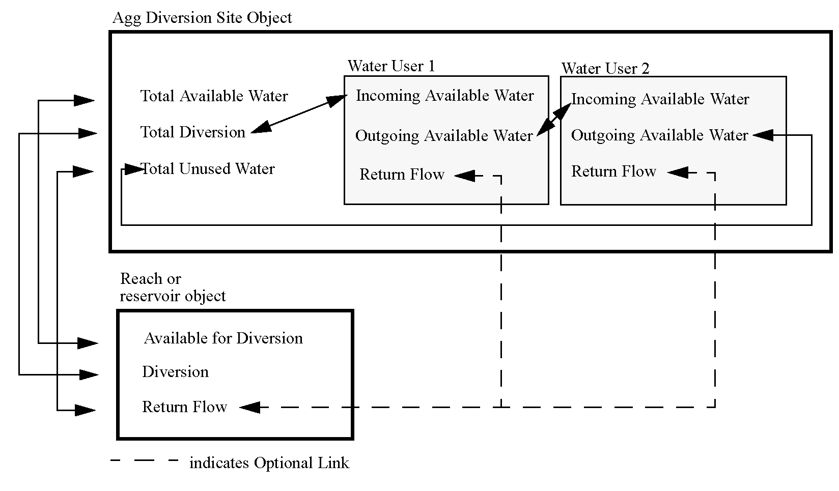
The Sequential Structure models a group of Water Users based on an order of allocation—perhaps by senior water right, for example.
The Agg Diversion Site diverts a bulk amount of water, from a reach or reservoir, and passes it to the first Water User, who takes its requested amount, if possible, and passes the remaining water on to the next user. In this way, the junior users may get only part or none of their requested amount. Excess is returned to the Agg Diversion Site, via the Total Unused Water slot. Each water user processes its delivered amount, and all return flows are handled on a per-Water User basis; that is, each Water User links its returns back to the river individually.
Optionally, you can create a link between Return Flow and the reach or reservoir. If no link is specified, the Return Flow is included in the Incoming Available Water for the next Water User. The Outgoing Available Water from the last Water User, including Return Flow if it is not linked, is linked to the Total Unused Water slot.
Figure 3.2 Sequential links
Slots Specific to This Method
Total Available Water
Type: Series Slot
Units: FLOW
Description: signifies the water available for diversion from the reservoir or reach to which the diversion is connected.
Information: Set by link propagation from the diverted object. The user is responsible for linking this slot with the object from which the water is diverted.
I/O: Optional; Can be input when it is not linked.
Links: May be linked to the Available For Diversion slot on a Reach object or reservoir, the Outflow slot on a Diversion object, or the Available Flow slot on a Distribution Canal.
Total Depletion
Type: Series Slot
Units: FLOW
Description: sum of the Depletion slots for all Water Users
Information:
I/O: Output only
Links: Usually not linked
Total Depletion Requested
Type: Multislot
Units: FLOW
Description: a multislot showing the Depletion Requested for each Water User as well as the sum of all requested depletions.
Information: Used for all linking structures.
I/O: Optional; Can be input when there are no Water User elements and it is not linked.
Links: Usually not linked
Total Depletion Shortage
Type: Series Slot
Units: FLOW
Description: sum of the Depletion Shortage Slots for all Water Users
Information:
I/O: Output only
Links: Usually not linked
Total Diversion
Type: Series Slot
Units: FLOW
Description: denotes the total water diverted to the Water Users.
Information: Must be linked, by the user, to the Diversion slot on the reach/reservoir being diverted from.
I/O: Optional; Must be input if Total Diversion Requested is not given.
Links: Must be linked to the Diversion slot on a Reach object or reservoir (if it is diverting from one of these objects).
Total Diversion Requested
Type: MultiSlot
Units: FLOW
Description: a multislot showing the Diversion Requested for each Water User as well as the sum of all requested diversions.
Information: Used for all linking structures.
I/O: Optional; Can be input when there are no Water User elements and it is not linked.
Links: May be linked to the Diversion Request slot on a Diversion Object, the Downstream Delivery Request slot on an upstream AggDistributionCanal, or the Total Delivery Request slot on a downstream AggDistributionCanal.
Total Diversion Shortage
Type: Series Slot
Units: FLOW
Description: sum of the Diversion Shortage slots for all Water Users
Information:
I/O: Output only
Links: Usually not linked
Total Unused Water
Type: Series Slot
Units: FLOW
Description: represents the unused water (surface return flow plus any non-diverted water) after all Water Users have processed their requests.
Information: Set by engineering methods after the Water Users dispatch. It is linked, by RiverWare to the Outgoing Available Water from the last Water User.
I/O: Output only
Links: Return Flow on the object being diverted from.
Total Surface Return Flow
Type: Series Slot
Units: Flow
Description: represents the surface water return flow. It is set equal to the Surface Return Flow of the last element on the aggregate. This is not necessarily the same as the Total Unused Water.
Information:
I/O: Output only
Links: Linkable
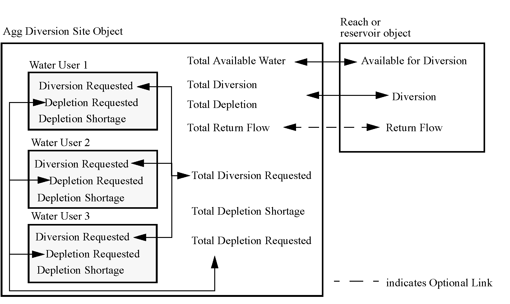
The Lumped Structure models a group of Water User’s requests as a single lumped sum. The individual requests are summed in the Total Diversion Requested slot on the Agg Diversion Site, and a comparison is made with the Total Available for Diversion slot. If the total request can be met, the Diversion slot is set to that amount; if not, the Diversion slot is set to the Total Available for Diversion amount.
In this scheme, the Return Flow is also lumped. The Total Depletion Requested slot tracks the sum of the individual Water User’s consumption requests. If a total deficit occurs in the Diversion, the Return Flows are recalculated based on the ratio of the Total Depletion Requested to the Total Diversion Requested. The Total Depletion Shortage is computed as the difference between Total Depletion Request and Depletion. The Total Depletion Shortage is then used to allocate the shortage to the member elements proportional to their depletion request.
It is not necessary to use Water User elements with this linking structure. If desired, Total Diversion Requested and Total Depletion Requested can be input directly by the user. However, it is often desirable to use one or more Water User objects for this purpose.
Figure 3.3 Lumped links
Slots Specific to This Method
Total Available Water
Type: Series Slot
Units: FLOW
Description: signifies the water available for diversion from the reservoir or reach to which the diversion is connected
Information: Set by link propagation from the diverted object. The user is responsible for linking this slot with the object from which the water is diverted.
I/O: Optional; Could be input if not set from link.
Links: May be linked to the Available For Diversion slot on a Reach object or reservoir, the Outflow slot on a Diversion object, or the Available Flow slot on a Distribution Canal.
Total Depletion
Type: Series Slot
Units: FLOW
Description: The total amount consumed by the agg.
Information: Computed typically as Total Diversion minus Total Return Flow
I/O: Output only
Links: Usually not linked
Total Depletion Requested
Type: Multislot
Units: FLOW
Description: a multislot showing the Depletion Requested for each Water User as well as the sum of all requested depletions.
Information: Used for all linking structures.
I/O: Optional; Can be input when there are no Water User elements and it is not linked.
Links: Usually not linked
Total Diversion
Type: Series Slot
Units: FLOW
Description: denotes the total water diverted to the Water Users
Information:
I/O: Optional; must be input if Total Diversion Requested is not given.
Links: Must be linked to the Diversion slot of a Reach object or a reservoir (if diverting from one of these objects).
Total Diversion Requested
Type: MultiSlot
Units: FLOW
Description: a multislot showing the Diversion Requested for each Water User as well as the sum of all requested diversions.
Information: Used for all linking structures.
I/O: Optional; Can be input when there are no Water User elements and it is not linked.
Links: May be linked to the Diversion Request slot on a Diversion Object, the Downstream Delivery Request slot on an upstream AggDistributionCanal, or the Total Delivery Request slot on a downstream AggDistributionCanal.
Total Return Flow
Type: Series Slot
Units: FLOW
Description: represents the portion of the water diverted to water users which is not consumed
Information: It is the user’s responsibility to specify what is done with this data. If it is not linked to another object (that is, back to the reach/reservoir Return Flow slot), it is lost from the system.
I/O: Output only
Links: May be linked to the Return Flow slot on any object or the Inflow slot on a Groundwater Storage object.
Total Depletion Shortage
Type: Series Slot
Units: Flow
Description: Represents the difference between Total Depletion Requested and Total Depletion.
Information: Computed as Total Depletion Requested - Total Depletion
I/O: Output Only
Links: NA
Revised: 01/11/2023