
Engineering Objects
Reservoirs: Modifications were made as follows
Beginning of Target Operation
The Target Operation code was rewritten to include a flag marking the Beginning of Target. A user-defined Beginning of Target timestep is marked with a TB, or Target Begin, flag in the Storage or Pool Elevation Edit Slot dialog. When solving a target operation, RiverWare searches backwards from the Target time until it finds a valid Target Begin flag. The Target Operation is solved using the value from the timestep prior to the Target Begin flag as an initial condition. If the timestep prior to the Target Begin does not have a valid Storage or Pool Elevation, or a valid input value exists between the Target Begin and the Target, the simulation aborts with an error. Likewise, if the Target Begin or Target timestep is already determined, simulation aborts. If no Target Begin flag is specified, RiverWare searches backwards to the first valid value and solves the Target Operation with this initial condition.
When a beginning of target is assumed in this manner, RiverWare marks the timestep where the Target Operation actually begins with a tb (lowercase) flag in the Open Slot dialog. This flag is treated as an output, and is automatically cleared at the start of the next run. Setting a Target Operation from an SCT generates both the Target and Target Begin flags, and clears any previous Target Operations which overlapped with the new range.
Figure 41.1 Prior to Target Operation
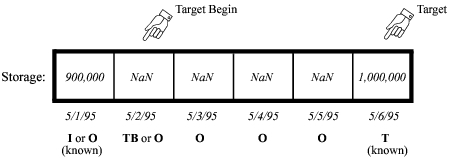
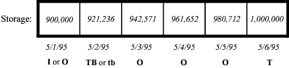
Figure 41.2 After Target Operation
Models previously built under PRSYM do not have Target Begin flags. These models will solve as they did before. RiverWare searches backwards until it finds a valid value and assumes a Beginning of Target time immediately after the valid value. In certain cases, however, models may have previously been overdetermined. Some older models may be overwriting Inflows or Outflows set by a Target Operation earlier in the run. This is caused by the Target Operation searching backwards too far for a beginning of target value which is not yet known. Due to dispatching order and other Target Operations, new Inflows or Outflows may be calculated which invalidate the original Target Operation. These modeling errors will now produce a “Setting Slot from multiple sources” message and abort simulation. The Target Operation may be corrected by explicitly setting a Target Begin flag at a timestep following the overdetermination.
Target Operation Calculation Category
The TargetOperationCalculationCategory has been expanded to all Reservoir objects. This Category was previously available only on Power Reservoirs. The noTargetCalc Method, which performs no calculations, has also been added to the two existing Methods and is now the default Method for this Category. Setting a Target Operation with the noTargetCalc Method selected will produce an error and abort simulation.
Hydrologic Inflows
A new User Method called noHydrologicInflow has been added to all Reservoirs. This is now the default Method for the HydrologicInflowCalculationCategory. This Method is used to model Reservoirs without the influence of hydrologic inflows, instantiates no slots, and requires no data.
The solveHydrologicInflow Method is no longer available on SlopePowerReservoirs and PumpedStorageReservoirs. Although the Method was previously selectable, it would not solve for timesteps where Hydrologic Inflow was not given on these Reservoirs.
The inputHydrologicInflow User Method has been modified not to initialize any linked slots at the Beginning of Run. The method previously initialized any unspecified Hydrologic Inflows and Hydrologic Inflow Adjust values to zero, and calculated the Hydrologic Inflow Net. It now checks that these slots are not linked prior to making any assignments. This allows values to propagate from other objects before dispatching.
Sediment Calculation
A new User Method Category called Sediment Calculation has been added to all Reservoirs. The Category is used to enable algorithms which adjust reservoir Elevation Volume and Elevation Area relationships in response to sediment inflow. There are two Methods available for selection within this Category, the default No Sediment Calc and CRSS Sediment Calc. The default Method performs no computations. Models previously saved under PRSYM will produce identical results when the default No Sediment Calc Method is selected.
The CRSS Sediment Calc Method is a reservoir sediment distribution algorithm based on the US Bureau of Reclamation’s Empirical Area Reduction Method. Sediment distribution is calculated by an iterative loop in which a total volume loss is derived from an assumed top of sediment elevation. The volume loss and top of sediment elevation are recalculated at each iteration, until the volume loss is equal to the given sediment inflow. The loss at each iteration is determined by an algorithm which utilizes elevation/area and elevation/volume data for the reservoir in conjunction with an empirical equation. This equation requires user-specified parameters to indicate the portion of total area which is taken up by sediment at any given elevation. The equation dictates the shape of the accumulated sediment and has a close relationship to the elevation-volume and elevation-area characteristics of the reservoir. The new elevation/area and elevation/volume data is stored in a polynomial coefficient table. This table is recalculated after each timestep. The actual Elevation-Area and Elevation-Volume tables used by RiverWare are adjusted following convergence of the solution, but prior to the hydrologic simulation.
The CRSS Sediment Calc Method is modeled after sedimentation calculations performed by the US Bureau of Reclamation’s Colorado River Simulation System (CRSS) model. The Method is initialized during TIMESTEPBEGINRUN. The User Input Elev Area Data is used to create the initial Elevation Volume and Elevation Area Tables which are required by the simulation. The elevation increments at which the two tables’ values are generated are determined by the Elevation Vol_Area Table Increment slot value. The Method initialization also uses the User Input Elev Area Data to create the Elevation Area Table Used and Elevation Volume Table Used. These tables are used solely for recalculating sediment distribution in later timesteps. The elevation increments for these tables are equal to those of the User Input Elev Area Table. Variable table increments allow sedimentation parameters to be calculated with a different precision than that used for the general Elevation Area and Elevation Volume Tables.
Input data is critically important for this Method. The close relationship between the empirical area reduction equation and the shape of the reservoir (reflected in the elevAreaTableInput table) makes this Method very sensitive to input data. The physical characteristics of the given reservoir must be considered when choosing empirical parameters for this Method. The Bureau of Reclamation currently considers four types of reservoirs, each having a corresponding set of empirical area reduction parameters. The reservoir type classification is based on shape, the manner in which the reservoir is to be operated, and the size of the sediment particles to be deposited, with the primary emphasis on shape. Tables are used to classify the reservoirs based on these characteristics. Once the type has been established, the parameter values for that type can also be taken from tables in the literature. An incorrect set of parameters for a given reservoir will lead to an inability to achieve convergence on the sediment distribution.
It is also important to note that this Method does not recalculate Elevation Area or Elevation Volume Tables during time horizon dispatching such as Target Operations. Models which do not solve chronologically may produce errors due to incorrect Elevation Area and Elevation Volume Tables. Contact CASDWES staff for additional information before implementing this new Method.
Following is a list of slots relevant to this method, which includes the slot name in bold type, the (slot) as it appears in the code in parentheses, the slot type (Multislot, etc.), the unit type(s) in all caps (LENGTH, FLOW, etc.), a brief description of the slot in italics, and additional comments in plain type.
Slots with Required Input Data
• Sediment Inflow(sedimentInflow)
– SeriesSlot
– VOLUME
– volume of sediment flowing into the reservoir each timestep
• User Input Elev Area Data(elevAreaTableInput)
– TableSlot
– LENGTH vs. AREA
– initial Elevation Area relationship
– These values are initial conditions for the first timestep of the simulation. The table’s elevation increments will be used for all internal sedimentation calculations.
• Elevation Vol_Area Table Increment(tableIncrement)
– ScalarSlot
– LENGTH
– elevation increments for the generated Elevation Volume and Elevation Area Tables
– These tables often need more precise elevation increments than the sediment calculation tables.
• Sediment Distribution Coefficients(distributionReductionCoeff)
– TableSlot
– NOUNITS
– parameters for empirical equation governing sediment distribution
Output Slots
• Initial Elevation Area Table (initElevAreaTable)
– TableSlot
– LENGTH vs. AREA
– initial elevation area table
– This table is provided for comparison with initial data.
• Initial Elevation Volume Table (initElevVolTable)
– TableSlot
– LENGTH vs. VOLUME
– initial elevation volume table
– This table is provided for comparison with initial data.
• Elevation Area Table Used (elevAreaTableUsed)
– TableSlot
– LENGTH vs. AREA
– generated elevation area table for calculating sediment distribution
• Elevation Volume Table Used (elevVolTableUsed)
– TableSlot
– LENGTH vs. VOLUME
– generated elevation volume table for calculating sediment distribution
Sediment Functions
The following function is called within TIMESTEPBEGINRUN on the Reservoir object.
getInitialTable() This function performs initialization of the tables to be used in sediment calculations. The user-input elevAreaTableInput table is used in conjunction with the function simple_poly (see Sediment Functions) to generate a series of coefficient arrays. These coefficient values are then used in the following polynomial equation to calculate incremental volumes at given elevation points:

where ΔElev is the change in elevation between points in the elevAreaTableInput table. These volume values are used to create the initial Elevation Volume Table, required for initialization calculations in RiverWare. For consistency, incremental area values are recalculated using the same coefficient values in the function area_from_coeff (see below). These area values are then used to create the initial Elevation Area table, also required for initialization calculations.
The following functions are called within TIMESTEPBEGINTIMESTEP on the Reservoir object.
create_area_reduction() This function is called at the beginning of the area_reduction function (see below). It allocates memory storage for the local arrays used in subsequent calculations and copies elevation-area and elevation-volume data from the existing slots to these arrays. Slots are not used in the iterative calculations. This function then calls the relative_sediment (see below) function to calculate the proportion of the reservoir slice which consists of sediment for each elevation point.
area_from_coeff() This function is used to calculate areas at given elevations using the coefficients calculated in simple_poly (see Sediment Functions). It is called in both getInitialTable and area_reduction. The polynomial for calculating area values at elevation i is:

The area correction term is calculated within this function based on the elevation increment size and the coefficient values.
relative_sediment() This short function applies the empirical area reduction equation, using the user-input parameters, to calculate the proportion of the total area at a given elevation which is taken up by sediment. The equation uses a relative depth (depth of the given slice / total depth of the reservoir) passed in from the external call.
area_reduction() This function is the heart of the sedimentation calculations. It contains the iterative loop which distributes sediment in the reservoir until the estimated additional volume of sediment is equal to the sediment inflow at the current timestep.
create_area_reduction is first called to create and initialize the local variable arrays. Once elevation-area and elevation-volume data is in local arrays and relative sediment values are calculated for each elevation, the iterative convergence begins. A sediment elevation equal to the middle of the reservoir is used to seed the iteration for each timestep. This sediment elevation corresponds to the base of the distributed sediment load in the reservoir. A total area for this elevation is then calculated by the function area_from_coeff. For each elevation point above the sediment elevation, sediment areas are calculated. These sediment areas are determined from the relative sediment values previously solved in create_area_reduction, normalized to the relative sediment of the current base elevation guess. All area slices above the base elevation are adjusted to account for the space taken up by the current sediment load in the reservoir. All area slices below the base elevation are set equal to their total area.
Once the sediment has been distributed for the current sediment base elevation guess, the total volume of sediment is calculated using incremental elevation differences multiplied by the average sediment area for each increment. The estimated total sediment volume for the given timestep is equal to the sum of the incremental sediment volumes. This total volume is compared to the sediment inflow volume for the current timestep (the previous timestep’s sediment load). If the difference between the two volumes is within the convergence criterion, the iterative loop is exited. If the difference is not within the convergence criterion, the sediment elevation estimate is adjusted. If the calculated volume is greater than the actual volume, the sediment elevation is reduced by a fraction; if it is less than the actual volume, the sediment elevation is increased by a fraction. The steps described above are then repeated with the new sediment elevation.
Upon convergence, the Elevation Volume and Elevation Area Table slots are adjusted to reflect the new sediment distribution. This is done by subtracting the sediment areas and sediment incremental volumes from the existing areas and volumes in the tables.
revise_table() This function eliminates meaningless rows below the sediment elevation from the Elevation Volume and Elevation Area Tables.
simple_poly() This function calculates the polynomial coefficients (e.g. coeff[i]a1) that are used to determine area and volume values at given elevations. These coefficients are calculated based on elevation-area data, initially supplied by the User InputElev Area Data table and subsequently supplied by the existing Elevation Area Table slot.
area_table_increment() / vol_table_increment() These functions use interpolation to adjust the Elevation Area and Elevation Volume Table slots to the elevation increment specified by the user. It is generally expected that this increment will be smaller than that used in the calculations described above; the above calculations use the Elevation Volume Table Used and Elevation Area Table Used, which are incremented according to the User Input Elev Area Data table. The option of specifying a finer increment to be used by all other RiverWare hydrologic calculations saves computing time in the more approximate sedimentation calculations.
Outflow Maximum Capacity
A new flag has been added to compute the maximum possible Outflow from a Reservoir on a given timestep. Setting the Max Capacity flag on a Reservoir Outflow slot forces the Outflow to equal the sum of the maximum (Turbine) Release and the maximum Spill. This flag should be used with great care, as its effects may cause downstream reservoirs to exceed their operating ranges. The use of this flag also depends heavily on having a reliable and accurate Regulated Spill Table and Max Turbine Q or Max Release table in order to attain reasonable Outflow values.
The Max Capacity flag is set by highlighting a simulation timestep on the Outflow slot of a Reservoir and selecting Timestep I/O Max Capacity. RiverWare places an M at the selected timestep to indicate that the flag is active. This flag is treated as an INPUT, but does not require a value. If a valid Outflow value is present at the flagged timestep, it is ignored in the simulation; a new Outflow value is calculated and displayed at that timestep. This behavior is similar to the Max Capacity and Best Efficiency flags of the Energy slot and the Drift flags of the Regulated Spill and Bypass slots. A Reservoir which has the Outflow Max Capacity flag set may dispatch under any of the “givenOutflow” dispatch methods:
• solveMB_givenOutflowHW for Level Power, Slope Power, and Storage Reservoirs.
• solveMB_givenOutflowStorage for Level Power, Slope Power, and Storage Reservoirs.
• solveMB_givenInflowOutflow for Level Power, Slope Power, and Storage Reservoirs.
• solveMB_givenOutflow for Pumped Storage Reservoirs.
The Outflow Max Capacity flag may NOT be used on Reservoirs linked to a Canal, when solving for Hydrologic Inflow, or when solving a Target Operation.
The Outflow Max Capacity solution is iterative. The exact sequence of calculations in each iterative loop is dependent on the type of Reservoir and the selected Spill Calculation Method. In all cases, the maximum Spill and maximum controlled Release are calculated individually, then summed. If the selected Spill Method includes Regulated Spill, the current or previous Pool Elevation is used to look up the maximum Regulated Spill from the Regulated Spill Table. This value is set in the Regulated Spill slot, and the selected Spill Calculation Method is called. Any input Bypass and/or required Unregulated Spill are considered within the Spill Method. Next, the maximum release is calculated. If the Reservoir is a Power Reservoir, the selected Tailwater Calculation Method is executed to determine the Operating Head. This Operating Head or the Pool Elevation (in the case of Storage Reservoirs) is used to look up the maximum release from the Max Turbine Q or the Max Release table, respectively. Finally, the maximum release and the calculated Spill are added to determine the total maximum Outflow. This Outflow is used to mass balance the Reservoir. The iteration is repeated until Convergence is met or Max Iterations is exceeded.
CRSS Bank Storage
The CRSSBankStorageCalc User Method has been modified so that negative Bank Storage values are reset to zero. This change was made to more precisely match the Bureau of Reclamation’s CRSS solution method. Users should be aware that the Change in Bank Storage slot is NOT adjusted when the Bank Storage is reset to zero. Since the Change in Bank Storage is used in the Reservoir mass balance, the reported Bank Storage value may not agree with Reservoir conditions.
Pan and Ice Evaporation
A new User Method, called PanAndIceEvaporation has been added to the Evaporation and Precipitation Method Category of all Reservoirs. The Method is used to calculate evaporation from a reservoir whose surface may be partially covered with ice. The Method uses the Pan Ice Switch slot as an indicator of whether ice is present on the surface of the reservoir. A default 0.0 value in the Pan Ice Switch triggers the Method to solve for Evaporation as the product of the Pan Evaporation Coefficient, Pan Evaporation, and average Surface Area over the timestep. A value of 1.0 in the Pan Ice Switch triggers the Method to solve for Evaporation as the product of the Surface Area not blocked by Surface Ice Coverage, the average of the Min and Max Air Temperature, and the K Factor. In both cases, the Precipitation is calculated as the product of the Precipitation Rate and the average Surface Area over the timestep.
Following is a list of slots relevant to this method, which includes the slot name in bold type, the (slot) as it appears in the code in parentheses, the slot type (Multislot, etc.), the unit type(s) in all caps (LENGTH, FLOW, etc.), a brief description of the slot in italics, and additional comments in plain type.
Slots with Required Input Data
• Elevation Area Table(elevAreaTable)
– TableSlot
– LENGTH vs. AREA
– surface area of the reservoir for each given elevation
Slots with Optional Input Data
• Pan Ice Switch(panIceSwitch)
– SeriesSlot
– NOUNITS
– indicator of surface ice coverage for each timestep; 0.0 = no ice, 1.0 = ice
– This slot’s values default to 0.0 for any timesteps not specified by the user.
• Precipitation Rate(precipRate)
– SeriesSlot
– VELOCITY
– precipitation rate onto surface
– This slot’s values default to 0.0 for any timesteps not specified by the user.
• Pan Evaporation(panEvaporation)
– SeriesSlot
– VELOCITY
– evaporation rate from surface
– This slot is only required if the Pan Ice Switch is 0.0.
• Pan Evaporation Coefficient(panCoeff)
– TableSlot
– FRACTION
– weighing factor for pan evaporation rate
– This slot is only required if the Pan Ice Switch is 0.0.
• Surface Ice Coverage(iceCoverage)
– SeriesSlot
– FRACTION
– fraction of surface area which is covered by ice
– This slot is only used if the Pan Ice Switch is 1.0, and defaults to a value of 0.0 for any timesteps not specified by the user.
• Min Air Temperature(minTemperature)
– SeriesSlot
– TEMPERATURE
– minimum air temperature during the timestep
– This slot is only required if the Pan Ice Switch is 1.0.
• Max Air Temperature(maxTemperature)
– SeriesSlot
– TEMPERATURE
– maximum air temperature during the timestep
– This slot is only required if the Pan Ice Switch is 1.0.
• K Factor(kFactor)
– SeriesSlot
– LENGTHperTEMPERATURE
– factor relating average temperature to evaporation rate
– This slot is only required if the Pan Ice Switch is 1.0.
Output Slots
• Surface Area(surfaceArea)
– SeriesSlot
– AREA
– surface area of the reservoir at the end of the timestep
• Evaporation(evaporation)
– SeriesSlot
– VOLUME
– volume of water lost to evaporation
Power Reservoirs: Modifications were made as follows
Hydro Capacity
A new getHydroCap utility has been designed to calculate Hydro Capacity more accurately. Previously, HydroCapacity was calculated as the product of the Maximum Power Coefficient and the maximum Turbine Release at the current Operating Head. A shortcoming of this approach was that the Operating Head used to determine the Power Coefficient and maximum Turbine Release did not reflect the changes brought about by the Turbine Release itself. For the purpose of computing Hydro Capacity, an iterative solution accounting for the changes in Operating Head as a result of the Turbine Release-affected Tailwater Elevation is necessary.
The iterative solution uses the maximum Turbine Release at the current Operating Head to calculate the Tailwater Elevation. This value is then used to compute a new potential Operating Head. The iteration continues until the difference in Operating Head is less than Convergence or the Maximum number of Iterations is reached. The Maximum Power Coefficient is then looked up in the Max Power Coefficient table using the new theoretical value for Operating Head. The advantage to using this potential value for Operating Head compared to using the actual Operating Head of the current reservoir at that timestep should now be apparent. In addition, if the current reservoir’s Tailwater Base Value is linked to the Backwater Elevation of a downstream Slope Power Reservoir, getHydroCap will now solve for the Backwater Elevation of the downstream reservoir and use that value as the Tailwater Base Value when calculating Tailwater Elevation. Finally, if the Turbine Release prior to the start of Hydro Capacity calculations is equal to the value in the Max Turbine Q table for the current Operating Head, or if Energy is flagged as MaxCapacity, Hydro Capacity is explicitly set to the value in the Power slot.
As might be expected, this iterative solution process may produce significantly different Hydro Capacity values than the PRSYM executables. These differences are most pronounced in cases where Hydro Capacity is explicitly set to the value in the Power slot and when the Tailwater Base Value of the current reservoir is linked to a downstream Slope Power Reservoir’s Backwater Elevation. The user will not notice any changes in the GUI as a result of this modification. This utility requires no new data.
Unit Generator Power Limits
The unitGeneratorPowerCalc Method now allows a maximum Power generation Limit for each generator type to be specified. The power calculated for the generator type(s) using this method may not exceed the user-specified Power production Limits for that type(s). Power is calculated in the same manner it was before; however, turbine power may be reduced to remain within the Limit. Reductions in power have no effect on Turbine Release. Flow is routed through the turbines regardless of the maximum Power generation Limit. The Generators Available table series slot has been modified to accommodate the new data: it is now an aggregate series slot named Generators Available and Limit. This slot contains two columns for each unit—one for the availability and one for the power limit of the particular generator type.
Slots with Required Input Data
• Generators Available and Limit(generatorsAvailableLimitTable)
– AggSeriesSlot
– NOUNITS, POWER
– generator unit availability and power production limit
– This slot is a Series slot with two columns available for each unit.
Pump/Generator Unit Types
The way in which individual Pump and Generator Unit Types are defined has been modified for Pumped Storage and Power Reservoirs, respectively. The Pump Unit Types table and Generator Unit Types table now contain a single column. The Pump/Generator Number is no longer input into the first column; it is now automatically specified by the row label. The Pump/Generator Type is now specified in the first column. As rows are appended, the type of each new unit may be defined.
Checks are now performed during run intitialization to ensure that the number of units in the Pump/Generator Unit Types table matches the number of blocks in the Available Pumps/Generators Available and Limit tables. The number of unit types must also match the number of blocks in the Head vs. Pump Flow, Head vs. Pump Power, Best Generator Flow, Best Generator Power, Full Generator Flow, and Full Generator Power tables. If any of these criteria are violated, RiverWare aborts the run with a diagnostic error message.
Pumped Storage Reservoirs
Modifications were made as follows:
Gate Setting
A new User Method Category called Gate Setting has been added to Pumped Storage Reservoirs. The new Category is used to enable a Method which looks up a Gate Setting based on the current Operating Head. There are two Methods available for selection within this Category: the default No Gate Setting Calc and Calculate Gate Setting. The default Method performs no computations. Models previously saved under PRSYM will produce identical results when the Calculate Gate Setting Method is selected.
Two slots are instantiated for the Calculate Gate Setting Method:
Slots with Required Input Data
• Best Gate Setting(headBestGateSettingTable)
– TableSlot
– LENGTH vs. NOUNITS
– relationship between operating head and gate setting
Slots with Output Data
• Gate Setting(gateSetting)
– SeriesSlot
– NOUNITS
– index representing gate setting
Ground Water Storage
A new GroundWaterStorage object has been added to allow modeling of groundwater recharge, storage, and flow due to irrigation activities. The object is a simple underground storage container which fills with the groundwater portion of WaterUser return flow and spills based on a selected User Method. No attempt is made to account for Darcyian or aquifer properties. The Groundwater Object may be created by selecting its icon in the Palette and dragging it onto the workspace.
There are three general, or non-Method specific slots on the GroundWaterStorage object. Following is a list of slots relevant to this method, which includes the slot name in bold type, the (slot) as it appears in the code in parentheses, the slot type (Multislot, etc.), the unit type(s) in all caps (LENGTH, FLOW, etc.), a brief description of the slot in italics, and additional comments in plain type. They are:
• Inflow(inflow)
– MultiSlot
– FLOW
– groundwater recharge from water user diversions
• Outflow(outflow)
– SeriesSlot
– FLOW
– groundwater return to surface water
• Storage(storage)
– SeriesSlot
– VOLUME
– volume of groundwater stored
– An initial (beginning of run) value must be input.
The GroundWaterStorage object currently solves under one dispatch method only, solveGWMB_givenInflow. This dispatch requires that the current Inflow be known to solve. The Inflow may be input or linked to the GW Return Flow slot on a Water User Element. The calculated Outflow may be linked to the Return Flow or Local/Hydrologic Inflow slot on a Reach or Reservoir.
A User Method Category called GWOutflowCalc is available on the GroundWaterStorage object, used to enable algorithms which calculate Outflow. There are four Methods available for selection within this Category: the default none, TableFlow, LinearFlow, and ExponentialFlow. The default Method performs no computations and is not a valid selection.
The Table Flow Method iterates a mass balance calculation and a table lookup for Outflow based on the Storage, seen below, during the timestep. The iteration continues until Max Iterations is surpassed or the outflows found by both methods differ by less than Convergence.


Slots with Required Input Data
• Storage Outflow Table(storOutflowTable)
– TableSlot
– VOLUME vs. FLOW
– relationship between storage and outflow
Slots with Optional Input Data
• Max Iterations(maxIterations)
– TableSlot
– NOUNITS
– maximum number of times to iterate mass balance and table lookup
• Convergence(convergence)
– TableSlot
– NOUNITS
– stopping criteria for iterative solutions
Slots with Output Data
• Outflow(outflow)
– SeriesSlot
– FLOW
– outflow from groundwater storage
The Linear Flow User Method calculates Outflow as a linear function of the previous timestep’s Storage. This Outflow is then used in a mass balance to determine the new Storage. If a Max GW Capacity has been entered and the new Storage exceeds it, the excess Storage is reallocated. Any excess volume of water is added to the previously computed Outflow.

The GW Alpha Param has no units. The value input into this slot must be in terms of the proper units to convert from Storage to Outflow (unit type of TIME-1), given the user units for each of these slots. For example, when Storage and Outflow are displayed with user units of acre-ft and cfs, respectively, the GW Alpha Param value must be in units of cfs/acre-ft. No enforcement of units is performed in this Method.
Slots with Required Input Data
• GW Alpha Param(gwAlphaTable)
– TableSlot
– NOUNITS
– linear relationship between storage and outflow
Slots with Optional Input Data
• Max GW Capacity(maxGWCapacity)
– TableSlot
– VOLUME
– maximum groundwater storage
Slots with Output Data
• Outflow(outflow)
– SeriesSlot
– FLOW
– outflow from groundwater storage
The Exponential Flow User Method calculates Outflow as an exponential function of the previous timestep’s Storage. This Outflow is then used in a mass balance to determine the new Storage. If a Max GW Capacity has been entered and the new Storage exceeds it, the excess Storage is reallocated. Any excess volume of water is added to the previously computed Outflow.

The GW Alpha Param has no units. The value input into this slot must be in terms of the proper units to convert from Storage to Outflow (unit type of TIME-1 x (LENGTH3)β-1), given the user units for each of these slots. For example, when Storage and Outflow are displayed with user units of acre-ft and cfs, respectively, and the GW Beta Param is 2, the GW Alpha Param must be in units of cfs/acre-ft2. No enforcement of units is performed in this Method.
Slots with Required Input Data
• GW Alpha Param(gwAlphaTable)
– TableSlot
– NOUNITS (scalar)
– linear portion of relationship between storage and outflow
• GW Beta Param(gwBetaTable)
– TableSlot
– NOUNITS
– exponential portion of relationship between storage and outflow
Slots with Optional Input Data
• Max GW Capacity(maxGWCapacity)
– TableSlot
– VOLUME
– maximum groundwater storage
Slots with Output Data
• Outflow(outflow)
– SeriesSlot
– FLOW
– outflow from groundwater storage
Reaches
The existing Reach code has been revised to improve efficiency, structure, and readability. Most changes relate to the internal structure of the Reach object and will be completely invisible to users. The visible changes and enhancements which are of concern to users are listed below:
Slot Dependencies
Slots are now dependent on the user-selected routing Method. Only the slots required by the chosen routing Method will now appear in the Open Object slot list. This alleviates some previous confusion caused by unused slots in the object. Reaches are now consistent with all other RiverWare objects in only displaying slots which are required input or calculated within the method.
Local Inflow Calculation
The hydrologicInflowCalculationCategory, its User Methods, and the slot Hydrologic Inflow, have all been changed from “hydrologic” to “local” Inflow. This was done to be consistent with Reservoir objects which already used the “local” nomenclature. The User Methods are now named inputLocalInflow and calcLocalInflow. The renamed localInflowCalculationCategory is now dependent on the NoRouting User Method, since it is the only Routing Method which accounts for local inflows.
Stability in Routing Methods
Certain Routing Methods are inherently stable in their numerical schemes while others may be subject to considerable error. For conditionally unstable solution techniques, acceptable operating ranges may be determined analytically. Both the Muskingum-Cunge and the Macormack Methods now have stability checks based on user input parameters. An error message appears if the user has input values which could lead to instability.
Drying up due to Diversion
A new check has been added to prevent Reaches from drying up due to large Diversions in the kinematicRouting, muskingumCungeRouting, and macCormackRouting methods. RiverWare now aborts simulation with an error message when the Diversion from a Reach is equal to its Inflow in any of these Methods.
Time Lag Over determination
Potential overdetermination is now being checked in TimeLagRouting. The checks compare the mass balance calculated values against the existing input slot value. If the values differ, this is taken as an indication of competing solutions. An overdetermination error message appears, and the simulation is aborted. The checks take place after each mass balance calculation in the TimeLag User Method.
Variable Time Lag Routing Initialization
When solving for Outflow in the variableTimeLagRouting Method, unknown Diversion and Local Inflow values prior to the first simulation timestep are now assumed to be zero. These values are required to solve for the side flow contribution to the Reach Outflow. Consistent with the Diversion and Local Inflow of Reservoirs, these side flows now default to zero if not input.
SSARR Routing Method
A new routing Method, SSARRrouting, has been created for Reaches. This routing Method is a simple storage routing with storage time calculated based on a user-input polynomial. It calculates outflow based only on user input or linked inflow values. It does not use local inflow, diversion, or return flow for the calculation.
Slots with Required Input Data
• storage time exponent(powr)
– TableSlot
– NOUNITS
– exponent value for calculating storage time with simple polynomial
– This slot is used to calculate storage time in SSARR routing method.
• storage time coefficient (kts)
– TableSlot
– NOUNITS
– coefficient value for calculating storage time with simple polynomial
– This slot is used to calculate storage time in SSARR routing method.
• number of segments in reach (nseg)
– TableSlot
– NOUNITS
– number of segmental divisions along the length of the reach
– This slot is used to subdivide reach into segments for routing calculations.
Impulse Response Routing Method
The Impulse Response Routing Method now flags an error and aborts the run if the Inflow at the previous timestep is not known. A previous Inflow is required by this routing solution type and should be input or calculated.
Stage and Volume Calculation
A new User Method Category called stageVolumeCalculation has been added to Reaches objects. The Category is used to enable algorithms which calculate the water surface elevation at the top and bottom of a Reach as well as the volume of water contained in that reach. It is anticipated that this calculation will be used to determine the maximum diversion from gravity flow structures. The Category is only available when the timeLagRouting Method has been selected. There are two Methods available for selection within this Category, the default noCalc and tableLookUp. The default Method performs no computations. This Method Category is executed after the Reach Routing Methods and currently does not influence mass balance in any way.
The tableLookUp User Method calculates the Inflow Stage and Outflow Stage of a reach if these values are neither linked nor INPUT. The Inflow Stage Table and Outflow Stage Table are used to look up the water surface elevation based on the flow through the channel at that point. Once both Inflow and Outflow Stages have been computed, the Reach Volume is calculated based on the previous volume of water in the reach and the difference in Inflow and Outflow over the current timestep. An initial Reach Volume must be specified to solve this Method.
Slots with Required Input Data
• Reach Volume(reachVolume)
– SeriesSlot
– VOLUME
– volume of water contained in the reach
– An initial volume is required at the Initial timestep of the simulation. All other timesteps will be computed.
Slots with Optional Input Data
• Inflow Stage(inflowStage)
– SeriesSlot
– LENGTH
– water surface elevation at the top of the reach
– This slot may be input or calculated.
• Outflow Stage(outflowStage)
– SeriesSlot
– LENGTH
– water surface elevation at the bottom of the reach
– This slot may be input or calculated.
• Inflow Stage Table(inflowStageTable)
– TableSlot
– FLOW vs. LENGTH
– relationship between flow in channel and water elevation
– This table is not required if Inflow Stage is linked or input.
• Outflow Stage Table(outflowStageTable)
– TableSlot
– FLOW vs. LENGTH
– relationship between flow in channel and water elevation
– This table is not required if Outflow Stage is linked or input.
Mannings n and Energy Slope display precision
The default display precision for values in the Mannings Roughness n and Energy Slope slots has been increased to 5. These parameters are traditionally on the order of 10-2 and 10-3. The 5 digits beyond the decimal point are necessary to view the full precision of these parameters.
Diversions and Water Users
The Aggregate Diversion Site and Water Users have been extensively modified. Models previously built under PRSYM which contain Aggregate Diversions will need to be converted before running correctly under RiverWare Version 1.0. Several modifications are necessary.
Renaming of Slots
Seven slots on the Aggregate Diversion Site Object and the Water User Object have been renamed. In order to preserve the data in models previously built under PRSYM, a conversion script must be run before loading these model in this release. The Perl script, called modelConvert1.0, is included in the executable package for RiverWare Release 1.0. A Perl language interpreter is required to run this script. If you do not have Perl on your system, contact CADSWES for assistance in converting model files. The conversion script changes the following slots:
Object Type | Old Slot Name | New Slot Name | |
|---|---|---|---|
AggregateDiversionSite | Total Diversion Delivered | ‘ | Total Diversion |
AggregateDiversionSite | Total Consumed Flow | ‘ | Total Depletion Requested |
AggregateDiversionSite | Total Return Flows | ‘ | Total Return Flow |
Water User | Diversion Delivered | ‘ | Diversion |
Water User | Consumed Flow | ‘ | Depletion Requested |
Water User | Return Flows | ‘ | Return Flow |
Water User | Percent Return Flow | ‘ | Fractional Return Flow |
The script is executed by running it with the name of the model file to be converted as an argument. For example, to convert the model MyModel, simply type:
% modelConvert1.0 MyModel
The model is converted, and a backup of MyModel is created with the name MyModel.old.
Return Flow Calculation
A new User Method Category called returnFlowCalculation has been added to Aggregate Diversion Site Water User elements. The Category is used to enable algorithms which calculate the quantity of Return Flow from Water Users when the noStructure or sequentialStructure LinkStructures are selected. When the lumpedStructure LinkStructure is selected, Return Flow is not calculated for each Water User element; it is calculated on the Aggregate Object by subtracting the Total Depletion Requested from the Total Diversion Requested. There are four Methods available for selection within the returnFlowCalculation Category: the default None, Fraction Return Flow, Proportional Shortage, and Variable Efficiency. The default Method performs no computations, and no Return Flow is generated. It is not a valid selection.
The Fraction Return Flow Method calculates Return Flow as a fraction of the Diversion delivered.
Slots with Required Input Data
• Fractional Return Flow (fractionalReturnFlow)
– SeriesSlot
– NOUNITS
– portion of diversion returned as return flow
– This must be input as a fractional value between 0 and 1.
Output Slots
• Return Flow (returnFlow)
– SeriesSlot
– FLOW
– flow returning from the water user
The Proportional Shortage Method calculates Return Flow as the difference between the Diversion delivered and the Depletion Requested, scaled if a shortage exists. If the entire Diversion Requested is delivered, the Depletion is simply the Depletion Requested. If the Diversion Requested cannot be met, the Depletion is the Depletion Requested, scaled by the percentage of shortage in Diversion. The Depletion is a constant proportion of the Diversion, regardless of shortage. The Return Flow is the difference between the Diversion and the Depletion.
Slots with Optional Input Data
• Depletion Requested (depletionRequested)
– SeriesSlot
– FLOW
– requested amount of water to be completely consumed
– This slot does not require a value if Diversion Requested is zero.
Output Slots
• Depletion (depletion)
– SeriesSlot
– FLOW
– actual amount of water completely consumed
– This value is less than or equal to the Depletion Requested.
• Return Flow (returnFlow)
– SeriesSlot
– FLOW
– flow returning from the water user
The Variable Efficiency Method calculates Return Flow as the difference between the Diversion delivered and the Depletion Requested, up to a Maximum Efficiency. The theoretical efficiency of the requested depletion is the ratio of the Depletion Requested to the Diversion. If this theoretical efficiency is less than the Maximum Efficiency, the Depletion is granted. If the theoretical efficiency is greater than the Maximum Efficiency, the actual Depletion is reduced to exactly correspond to the Maximum Efficiency. Return Flow is the difference between the Diversion and the Depletion.
Slots with Required Input Data
• Depletion Requested (depletionRequested)
– SeriesSlot
– FLOW
– requested amount of water to be completely consumed
• Maximum Efficiency (maxEfficiency)
– TableSlot
– NOUNITS
– maximum portion of diversion to be completely consumed
– This must be input as a fractional value between 0 and 1.
Output Slots
• Efficiency (efficiency)
– SeriesSlot
– NOUNITS
– actual portion of diversion which is completely consumed
• Depletion (depletion)
– SeriesSlot
– FLOW
– actual amount of water completely consumed
– This value is equal to the Diversion times the Efficiency.
• Return Flow (returnFlow)
– SeriesSlot
– FLOW
– flow returning from the water user
Groundwater Return Flow
A new User Method Category called returnFlowSplitCalculation has been added to Aggregate Diversion Site Water User elements. The Category is used to enable algorithms which calculate the proportions of Surface Return Flow and GW Return Flow. This Category is only valid when a returnFlowCalculation Method is selected. There are three Methods available for selection within the returnFlowSplitCalculation Category: the default No Split, Split Return Flow Fraction, and Split Return Flow Efficiency. The default Method performs no computations. The Split Return Flow Efficiency Method is only valid when the Variable Efficiency returnFlowCalculation Method is selected.
The Split Return Flow Fraction Method splits Return Flow into surface and groundwater components according to the Fraction GW Return Flow.
Slots with Required Input Data
• Fraction GW Return Flow (fractionGw)
– SeriesSlot
– NOUNITS
– portion of return flow which seeps into groundwater
– This must be input as a fractional value between 0 and 1.
Output Slots
• GW Return Flow (gwReturnFlow)
– SeriesSlot
– FLOW
– actual amount of return flow which seeps into groundwater
• Surface Return Flow (swReturnFlow)
– SeriesSlot
– FLOW
– actual amount of return flow which remains on the surface
The Split Return Flow Efficiency Method splits Return Flow into surface and groundwater components according to the computed Efficiency, Maximum Efficiency, and the GW Split Adjustment Factor. This method is based on the USBR return flow split calculation. The groundwater portion of the Return Flow is found by:

Slots with Required Input Data
• GW Split Adjust Factor (gwSplitAdjust)
– TableSlot
– NOUNITS
– adjustment to efficiency of return flow seeping into groundwater
– This must be input as a fractional value between 0 and 1.
Output Slots
• GW Return Flow(gwReturnFlow)
– SeriesSlot
– FLOW
– actual amount of return flow which seeps into groundwater
• Surface Return Flow(swReturnFlow)
– SeriesSlot
– FLOW
– actual amount of return flow which remains on the surface
–
Diversion Request
Water Users and lumped structure Aggregate Diversion Sites now assume a Diversion Requested of zero if not set by the user. This allows the object to dispatch in cases where the user has not supplied enough data.
Negative Water User Return Flows
Negative Return Flow values may now be calculated for Water Users when their Diversion Requested is zero. This situation occurs when the Consumed Flow is set to a value larger than the Diversion Delivered. Negative Return Flows were previously calculated only when Diversion Requested was non-zero.
Total Diversion Requested, Total Depletion Requested, and Total Depletion
The slots Total Diversion Requested and Total Depletion Requested have been added to Aggregate Diversion Sites for all Linking Structures. These MultiSlots sum the diversion and depletion requests from individual Water User elements. The slots will not contain a value if any of the element values at that timestep are invalid. The slot values are not adjusted during shortages, when the diversion and depletion requests may not be met.
The slot Total Depletion has been added to Aggregate Diversion Sites for Lumped and Sequential Structures. This SeriesSlot is set equal to the sum of the Depletion slots of individual Water User elements. The Total Depletion slot will not contain a value for any timestep at which any of the element Depletion values are invalid. The slot value reflects any adjustments made to individual Depletions in time of shortage.
Revised: 07/05/2022