
Reach Seepage
The Reach Seepage category is used to model seepage from a reach. The seepage is calculated at the top (upstream) end of the reach. All methods allow seepage to be input or set by a rule. When input or set by a rule, seepage is not recalculated by the method.
This method is available only when No Routing is selected in the Routing category.
This is the default method. It performs no seepage calculations.
There are no slots specific to this method.
Seepage is calculated as a fraction of the Inflow to the reach.
Slots Specific to This Method
Maximum Seepage
Type: Table
Units: FLOW
Description: represents the maximum amount of flow that can be lost as seepage
Information:
I/O: Required input
Links: Not linkable
Seepage
Type: Series
Units: FLOW
Description: The calculated amount of flow lost as seepage
Information: Subtracted from the Inflow value to calculate Outflow.
I/O: Input, Output, or Rule
Links: May be linked to the Inflow slot on the Groundwater Storage object.
Seepage Flow Fraction
Type: Table
Units: NO UNITS
Description: Represents the fraction of Inflow that is lost as seepage
Information: A decimal value that is greater than or equal to zero and less than one.

I/O: Required input
Links: Not linkable
This method uses variable parameters to model seepage. Seepage is calculated as a fraction of the Inflow for each time step.
Slots Specific to This Method
Maximum Seepage
Type: Table
Units: FLOW
Description: represents the maximum amount of flow that can be lost as seepage
Information:
I/O: Required input
Links: Not linkable
Seepage
Type: Series
Units: FLOW
Description: the calculated amount of flow lost as seepage
Information: Subtracted from the Inflow value to calculate Outflow.
I/O: Input, Output, or Rule
Links: May be linked to the Inflow slot on the Groundwater Storage object.
Variable Seepage Flow Fraction
Type: Series
Units: decimal
Description: a time series of values representing the fraction of Inflow that is lost as seepage
Information: Entered as a decimal value that is greater than or equal to zero but less than one.
I/O: Optional; defaults to 0.0 if not input.
Links: Not linkable

Each Reach may have horizontal seepage to multiple drains or to shallow groundwater aquifers with unique drainage characteristics. Horizontal seepage to individual drains is calculated using Darcy’s Law, as follows:

The Seepage slot is set as the sum of horizontal seepage to all drains. An Aggregate Reach object can be used to simulate discrete reaches or reach segments for which varying seepage characteristics are known.
Slots Specific to This Method
Seepage
Type: Series
Units: Flow
Description: the calculated amount of flow lost as seepage
Information: Seepage is subtracted from the Inflow value to calculate Outflow.
I/O: Input, Output, or Rule
Links: May be linked to the Inflow slot on the Groundwater Storage object. This should only be done when groundwater is the only drain to which seepage flows.
Stage vs Horiz Bank Seepage Area
Type: Table
Units: Flow Vs. area
Description: relates the reach avg stage to the horizontal bank area through which seepage flows in the vertical direction to each drain
Information: You can add additional columns when more than one drain is present. If the bank seepage area is constant, two extreme values for stage with the same bank seepage area will insure that tale interpolations return this value.
I/O: Required input
Links: Not linkable
Horiz Hydraulic Conductivity
Type: Table
Units: VELOCITY
Description: the horizontal hydraulic conductivity of the medium through which seepage flows
Information: You can add additional columns when more than one drain is present.
I/O: Required input
Links: Not linkable
Distance to Drain
Type: Table
Units: length
Description: the horizontal distance from the reach to the drain.
Information: This value is assumed to be constant. You can add additional columns when more than one drain is present.
I/O: Required input
Links: Not linkable
Method Details
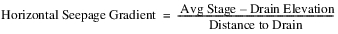
The Horizontal Gradient Seepage method requires that a Stage method be selected. It also has a dependent method category, the Drain Elevation method category. The reach horizontal bank seepage area through which seepage can flow to each drain in the horizontal direction is calculated using a stage/bank seepage area table interpolation. The horizontal hydraulic conductivity of the medium adjacent to each drain is entered by the user. The horizontal seepage gradient for each drain is calculated using the following equation:
Vertical gradient seepage is also calculated using Darcy’s Law; see Horizontal Gradient Seepage for details.
Slots Specific to This Method
Seepage
Type: Series
Units: FLow
Description: the calculated amount of flow lost as seepage
Information: Seepage is subtracted from the Inflow value to calculate Outflow.
I/O: Input, Output, or Rule
Links: May be linked to the Inflow slot on the Groundwater Storage object if groundwater is the only drain to which seepage flows.
Vert Hydraulic Conductivity
Type: Table
Units: VELOCITY
Description: the vertical hydraulic conductivity of the medium through which seepage flows
Information:
I/O: Required input
Links: Not linkable
Vert Hydraulic Gradient
Type: Series
Units: No units
Description: the gradient through which seepage flows to the vertical drain
Information:
I/O: Required input
Links: Not linkable
Vert Channel Surface Area
Type: Series
Units: AREA
Description: the surface area of the reach channel bottom through which seepage may flow in the vertical direction
Information:
I/O: Required input
Links: Not linkable
The Horizontal and Vertical Gradient Seepage method sums horizontal and vertical seepages.
This method is a composite of the Horizontal Gradient Seepage and Vertical Gradient Seepage methods. When it is selected all of the slots for the Horizontal Gradient and Vertical Gradient Seepage methods (above) are instantiated.
The Seepage and Riparian CU Loss method is available only when Specify Local Inflow, Solve Outflow; or No Local Inflow, Solve Outflow is selected from the Local Inflow and Solution Direction category.
This method sets the Leakage slot either from the user—as input or by a rule—or calculated from Seepage and Riparian CU Loss with the following calculation:
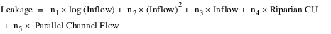
where n1, n2, n3, n4, and n5 are coefficients held in a table slot. For the Leakage calculation, if the inflow value is negative, it will be assumed to be zero.
The Seepage slot is set to the result of subtracting Riparian CU from the Leakage slot.

The Riparian CU Loss slot is set to the minimum of the Riparian CU and the Leakage. Here, if the calculated Leakage is negative it is assumed to be zero.

Note: The Leakage calculation uses the Inflow value in user units. The value set in the LogInflowCoeff column and the value and units in the InflowSqrdCoeff column of the Evaporation Data slot (n1 and n2), as set by the user, must be consistent with the user units for the Inflow slot. Changing the user units on the Inflow slot will produce a different result. There will not be an automatic conversion of the Coefficient values.
Slots Specific to This Method
Seepage
Type: Series
Units: Flow
Description: difference of Leakage and Riparian CU
Information: Subtracted from the Reach Inflow value to calculate Outflow.
I/O: Input, Output, or Rule
Links: Linkable
Leakage
Type: Series
Units: Flow
Description: amount of incoming water lost to various sources.
I/O: Input or Output.
Links: Linkable
Riparian CU
Type: Series
Units: Flow
Description: flow rate of the consumptive use in the riparian area
Information: Riparian CU is used in the Leakage calculation of the Reach and the Riparian CU Loss calculations.
I/O: Required input
Links: Not linkable
Riparian CU Loss
Type: Series
Units: Flow
Description: the minimum of Leakage and Riparian CU
Information: Subtracted from the Reach Inflow value to calculate Outflow
I/O: Output only
Links: Not linkable
Seepage and Riparian CU Loss Coeff
Type: Table
Units: None, 1/Flow, None, None, None
Description: relates the month to a set of five coefficients with the following names and units: LogInflowCoeff [NONE], InflowSqrdCoeff[1/FLOW], InflowCoeff [NONE], CUCoeff [NONE], ParChanFlowCoeff[NONE]. the table has twelve rows, one for each month of the year.
Information: These coefficients are specific to the encoded Leakage equation. The values must be consistent with the user units for the Inflow slot. If the user units on the Inflow slot are changed, the values in this slot must be changed manually to correspond to the new units. Otherwise different results will be produced
I/O: Required input
Links: Not linkable
Parallel Channel Flow
Type: Series
Units: Flow
Description: flow rate of upstream diversion to a parallel channel
Information: Available on Reach objects for use in Leakage calculations. Typically linked to flow in a parallel channel. Dispatch slot.
I/O: May be output or input. If it is not linked or user input, it will be assumed to be zero.
Links: Linkable
A method to compute the river stage based on the reach inflow and outflow values must be selected in the Stage Calc Category. If no stage method is selected, the Head Based Seepage method terminates with an error.
The Head Based Seepage method will compute the seepage based on the head in the river relative to the groundwater head. If the groundwater head is below the streambed elevation then the seepage will be computed based on the head in the river relative to the streambed bottom.
Slots Specific to This Method
Seepage
Type: Series Slot
Units: flow
Description: The river loss or gain from groundwater
Information: A positive number represents a losing reach while a negative number represents a gaining reach
I/O: Input, Output, or Rule
Links: Usually linked to the groundwater object
Previous Water Table Elevation
Type: Series Slot
Units: length
Description: The previous elevation value computed by the connected groundwater object
Information: Seepage is computed based on the difference between the current river stage and the previous groundwater elevation
I/O: Output only
Links: Linked to the Previous Elevation slot on the connected groundwater object
Conductance
Type: Scalar slot
Units: area per time
Description: The riverbed conductance
Information: The conductance is defined as the hydraulic conductivity of the streambed material, multiplied by the width of the streambed bottom, multiplied by the length of the stream segment, divided by the streambed thickness (Conductance = KwL/m).
I/O: Input or computed as specified; see Reach Conductance.
Links: Not linkable
Streambed Elevation
Type: Scalar Slot
Units: length
Description: The elevation of the stream bed at the center of the reach segment (that is, average stream bed elevation)
Information: Should have the same datum as Stage and the Previous Water Table Elevation
I/O: Required input
Links: Not linkable
Conductance Factor
Type: Series Slot with Periodic Input
Units: Fraction
Description: The Conductance is multiplied by this factor in the calculation Seepage. It can be used to model variable Conductance.
Information: If the slot is NaN, a default of 1 is used in the calculation of Seepage. The slot remain as NaN.
I/O: Optional input or rules
Links: Not typically linked
Method Details
The Head Based Seepage method computes the seepage to groundwater using one of the following equations.
• If the Previous Water Table Elevation is greater than the Streambed Elevation.

• If the water table elevation at the previous timestep is below the Streambed Elevation.

Note: The preceding equations use the water table elevation at the previous timestep. This simplification is done to avoid iteration problems that would result if the current groundwater elevation was used. A positive seepage is limited to be less than or equal to the Inflow to the reach.
Revised: 07/05/2022