
Dispatch Methods
This dispatch method is used for Single Computed Outflow calculations only. With a given Inflow, the dispatch method can execute to calculate Outflow and Storage. The required knowns and unknowns (at the current timestep) are listed below.
Required Known Slots
• Inflow
Required Unknown Slots
• Outflow
• Storage
Method Details
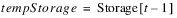
First the previous timestep’s Storage is checked. If it is not known, the method is exited because a previous Storage value is required for any of the user methods in the Groundwater Outflow category to execute successfully. Otherwise, if the Storage is less than the lower bound, the run is stopped with an error. The lower bound is specified on the Storage slot, using the View and then Configuration menu as shown.
Figure 15.6 Screenshot of the lower bound configuration
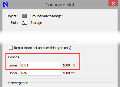
If no lower bound is specified, a value of zero is used to match historic results.
Next, the dispatch method executes the selected GW Deep Percolation method and the selected Groundwater Outflow method. If the selected Groundwater Outflow method is ImpulseResponseOutflow, the dispatch method next executes the selected Impulse Response Components method and Negative Outflow Adjustment method.
A local variable, storage flow, is calculated as the previous timestep’s Storage value divided by the length of the current timestep. This represents the flow rate required to drain the groundwater of all its stored water in the current timestep. If the calculated Percolation plus Outflow is greater than storage flow, a warning is posted and the following calculations take place.
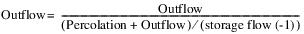
Outflow is recalculated as follows:
However, if Input Percolation is selected in the GW Deep Percolation category, Outflow is recalculated as follows:

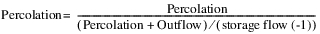
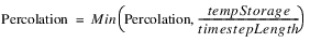
Percolation, if not input, is recalculated as follows. A warning is posted to notify you of this change.
This prevents the storage from going negative. If there is no method selected to calculate Percolation, it is assumed to be zero.
The Groundwater Pumping method is then executed to compute Available For Pumping at the current timestep based on the previous Storage and the current Outflow and Percolation.
Percolation (if applicable), Outflow, and Pumped Flow (if applicable) are then converted to volumetric values by multiplying them by the length of the timestep. Storage is then calculated using the following mass balance equation:

If the computed Storage is less than the lower bound, a warning message is posted but the run is not stopped. The lower bound is specified on the Storage slot, using the View and then Configuration menu. See Figure 15.6. If no lower bound is specified, a value of zero is used, to match historic results.
This dispatch method is used for Head Based Groundwater Grid calculations only. The required knowns and unknowns (at the current timestep) are listed below.
Required Known Slots
• Elevations Left/Right/Upstream/Downstream Previous
There is a different set of dispatch conditions for each of the methods in the Lateral Link Direction category. If the No Linked Objects method is selected, then the elevations slots are not applicable.
Required Unknown Slots
• Storage
Method Details
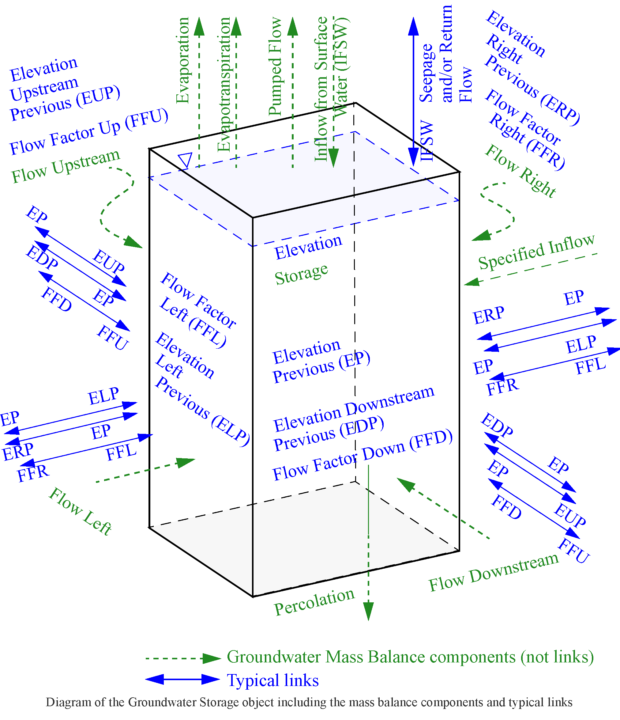
The Solve given Inflow from Surface Water dispatch method computes current Storage and Elevation values based on the mass balance equation described below. Following are the steps performed in the dispatch method.
Figure 15.7 Groundwater Storage object, including the mass balance components and typical links
Conditions for dispatching are as follows:
• The dispatch method will execute when the Inflow From Surface Water and the Elevation Upstream/Downstream/Right/Left Previous slots are known. Depending on the number of connected groundwater objects, one or all of the Elevation Upstream/Downstream/Right/Left Previous slots may be active.
• If the Inflow From Surface Water slot is not being used (is not linked) it is set to zero for all timesteps at the beginning of the run.
• Whenever a new value is received for Inflow From Surface Water or any of the Elevation Previous slots, the object will redispatch.
Steps in the dispatch method are as follows:
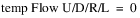
Note: For the remainder of this section, the term U/D//R/L is used to represent a slot or variable for any or all of the combinations of the four directions, for example Flow U/D/R/L to represent Flow Upstream, Flow Downstream, Flow Right and Flow Left. The set of directions that are actually used depends on the method selected in the Lateral Link Direction category.
1. If the previous Storage is not known, the method exits and waits. In the beginning of run, there is a check to ensure that you input an initial storage value and initial Elevation value.
2. A tempStorage local variable is set equal to the previous timestep Storage. This is updated at each step by the inflows and outflows to track the running mass balance.
3. Get Preliminary Lateral Flows: A method is called to compute the preliminary, unadjusted lateral flows, temp Flow Upstream/Downstream/Right/Left. One or all of these slots may be computed based on the number of connected groundwater objects. For any Flow slot that is not in use, the corresponding temp Flow value gets set to zero.

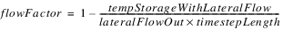
4. Add Lateral Inflows: All of the positive lateral flows (lateral inflows) are added to the running mass balance. The corresponding Flow Factor is applied. If the Flow Factor is NaN, it is assumed to be 1.0, but it is not set. If the Flow Factor is not linked, it is unused and is assumed to be 1.0.
FOR (U/D/R/L)
IF (temp Flow U/D/R/L > 0)


END IF
5. Add Inflow from Surface Water: Inflow from Surface Water is always used as is. If the value is negative and causes the tempStorage to become negative, a warning will be issued.

6. Add Specified Inflow: Specified Inflow is always used as is. If the value is negative and causes the tempStorage to become negative, a warning will be issued.

7. Subtract Pumped Flow: If the Input Pumped Flow method is selected, and the Pumped Flow slot is linked to another object(s) but does not contain a value, the method exits and waits for the linked water user object(s) to set Supplemental Diversion. These values are then passed back to the groundwater object through the Pumped Flow slot. If the Pumped Flow value is already present, then it is subtracted from the running mass balance. If no Groundwater Pumping method is selected, then Pumped Flow is not included in the mass balance.

8. Subtract Percolation: If the GW Deep Percolation method is selected, then it is called. Percolation is initially computed as discussed in the Head Based Percolation user method section; see Head Based Percolation. If Percolation is specified (input or set by rules), then it is always used as is. If the value is positive and causes the tempStorage to become negative, a warning will be issued. Otherwise if Percolation is not specified, it is checked that it will not cause the tempStorage to become negative. Positive Percolation is flow out of the groundwater object.
IF Percolation is input or set by rules
Use Percolation as is
ELSE
Set the Percolation slot, but limit it to the amount of water remaining in tempStorage. Do not allow storage to become (more) negative.
IF (tempStorage <= 0)

ELSE
END IF
END IF

9. Subtract Evaporation: The Groundwater Evaporation method is executed. If the Wetted Sand Area Excluded is visible and linked but not valid, the Groundwater object exits the dispatch method and waits for the connected object to compute a value. Otherwise, evaporation is incorporated into the running mass balance with a check that it will not cause tempStorage to become negative.
IF (tempStorage <= 0)

ELSE

END IF

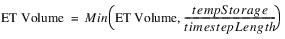
10. Subtract Evapotranspiration: The Groundwater Evapotranspiration method is executed and calculates a preliminary ET Volume. If ET Volume is specified (input or set by rules), then it is always used as is. If the value causes the tempStorage to become negative, a warning will be issued. Otherwise if ET Volume is not specified, it is checked that it will not cause the tempStorage to become negative.
IF ET Volume is input or set by rules
Use ET Volume as is
ELSE
Set the ET Volume slot, but limit it to the amount of water remaining in tempStorage. Do not allow storage to become (more) negative.
IF (tempStorage <= 0)

ELSE
END IF
END IF

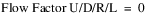
11. Incorporate Lateral Outflows: A preliminary storage value is calculated after incorporating all negative lateral flows (lateral outflows). If that value is negative and the Flow Factor U/D/R/L slots are linked, a Flow Factor is calculated that will result in a storage of 0. If the tempStorage before applying the lateral outflows was already negative, then the Flow Factor will be zero. The Flow Factor will propagate across the link to be applied to the corresponding lateral inflow on the linked groundwater object. If the resulting preliminary storage is non-negative, then the Flow Factor is assumed to be 1.0, but the slot value is not set. If the Flow Factor U/D/R/L slots are not linked, they will not get used, and thus any negative preliminary storage will remain as the final storage.
IF (tempStorage < 0)
IF (temp Flow U/D/R/L < 0)
END IF
ELSE
FOR (U/D/R/L)
IF (temp Flow U/D/R/L < 0)

END IF
END FOR

IF (tempStorageWithLateralFlow < 0)
IF (temp Flow U/D/R/L < 0 AND Flow Factor U/D/R/L is linked)


END IF
END IF
END IF
Note: This logic assumes that either none of the Flow Factor slots are linked, and thus the Flow Factor slots are not used, or all of the Flow Factor slots are linked appropriately to Flow Factor slots on adjacent Groundwater objects. If the linking of the Flow Factor slots is inconsistent, it could result in a gain or loss of mass.
12. Incorporate the final negative lateral flows into the running mass balance.
FOR (U/D/R/L)
IF (temp Flow U/D/R/L < 0)

END IF
END FOR
13. The final flow values are then set on the Flow U/D/R/L slots.

14. The final Storage slot value is computed by the following mass balance equation:

The groundwater flow, percolation, Inflow from Surface Water, Specified Inflow and pumped flow terms in the above equation are actually the volumes associated with those flow rates (flow rate multiplied by timestep length). Some of the terms may not be active depending on method selection (that is, ET Vol, Percolation, Pumped Flow).
If Storage is negative, a warning will be issued but the run does not terminate.
15. The Elevation slot is computed as follows:

16. The Elevation Previous slot is set at the next timestep given the current Elevation value. This will propagate to the Elevation Left/Right/Upstream/Downstream Previous slots on the connected groundwater objects. This will trigger the connected groundwater objects to dispatch at the next timestep.
17. The Previous Storage slot is set at the next timestep given the current Storage value. This is an invisible slot. It will trigger the current groundwater object to redispatch at the next timestep, if necessary.
18. If the Input Pumped Flow method is selected, and the Available For Pumping slot is linked to another object(s), Available For Pumping for the next timestep is computed from the current Storage with ET Volume and Percolation removed if they are already known. This value will then propagate to the linked water user objects which can then compute Supplemental Diversion on the next timestep. These values are then passed back to the groundwater object through the Pumped Flow slot.

Note: Mass Balance - The groundwater flows between the objects are only used to compute storage. So each individual object will mass balance, but the flow values are not transferred between objects. This is because the only linked slots are the Elevation Previous slots and Flow Factor slots. For these objects to mass balance, and for the groundwater system to mass balance, the conductance values must be identical for connected groundwater objects on either side of a given link. If you use the Compute Conductance method on each groundwater object, then adjacent conductances are guaranteed to be identical; see Compute Conductance.
This dispatch method is used for Head Based Boundary Condition solution type only. The purpose of this solution type is allow for linking of a groundwater network to a Reservoir. The required knowns and unknowns (at the current timestep) are listed below.
Required Known Slots
• Elevation Previous Left/Right/Upstream/Downstream
There is a different set of dispatch conditions for each of the methods in the Lateral Link Direction category. If the No Linked Objects method is selected, then the Elevation Left/Right/Upstream/Downstream Previous slots are not applicable.
Required Unknown Slots
Method Details
Following are the steps in the dispatch method.
1. The Elevation slot is set for the previous timestep:

The Elevation Previous value will typically be propagated across a link from the Reservoir Previous Elevation slot.
2. A method is called to compute Flow Upstream, Downstream, Left, and Right. One or all of these slots may be computed based on the number of connected Groundwater objects. These are computed based on the Elevation Previous and Elevation Left/Right/Upstream/Downstream Previous and Conductance Left/Right/Upstream/Downstream. The Flow Factor Left/Right/Upstream/Downstream is applied if it is not NaN. (The Flow Factor will be calculated by the linked Groundwater object using the Head Based Groundwater Grid solution type. If it is NaN, it is assumed to be 1.)

3. If a Deep Percolation method is selected, then it is called. Percolation is computed as discussed in the user method sections for the Deep Percolation category.
4. Finally the mass balance is performed to compute the Inflow from Surface Water:

Reservoir/Groundwater Object Interaction is a description of the typical Groundwater object and Reservoir interaction. It consists of three sets of objects. See Figure 15.8.
• Reservoir with Linked Seepage method (a)
• One Groundwater object with the Head Based Boundary Condition method (b)
• One to four laterally linked Groundwater objects solving using Head Based Groundwater Grid (c1-c4)
Figure 15.8
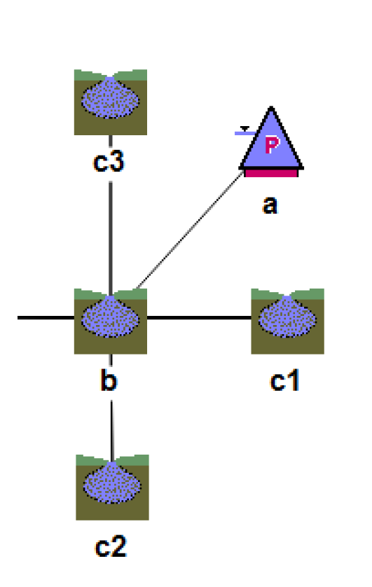
On the first timestep, the c1‑c4 get an Inflow from Surface Water and solve for Storage and Elevation given Elevation Previous values. Also, b solves given Elevation Previous which came across the link from the Reservoir as set on the Reservoir during initialization. A new Inflow from Surface Water is computed for b and propagates to the Reservoir.Seepage. The Reservoir dispatches once it has enough information and solves for Storage and Pool Elevation at t and sets Previous Pool Elevation at t+1. This propagates to Elevation Previous on b at t+1, which in turn propagates to Elevation Upstream/Downstream/Right/Left Previous on c1-c4 at t+1. This allows c1-c4 to solve at t+1, and b also solves at t+1 for Inflow from Surface Water. This linked value provides Reservoir.Seepage for the next timestep. The process continues through the run where the c1-c4 and b solve one timestep before the Reservoir is able to solve.
Revised: 06/04/2022