
Solution / Dispatching
Following is a description of the beginning of run and dispatching behavior when Layered Salt is selected.
Beginning of Water Quality Run
At the beginning of run, the scalar value for the Storage Capacity Upper is computed as follows:
(11.3) 
On the initial timestep, the upper and lower storage, and proportion are computed as shown in Equation 11.4 through Equation 11.9. Also, the Salt Conc Upper and Salt Conc Lower are checked for valid values on the initial timestep.
Required Known Slots
• Storage
• Inflow From Surface Water
• Elevation
• Elevation Previous Left/Right/Upstream/Downstream (depending on linked directions)
• Salt Conc Upper Previous
• Salt Conc Lower Previous
Required Unknown Slots
• Salt Conc Upper
• Salt Conc Lower
Method Details
This method requires any salt concentrations provided across links to be known; if they are not known, the dispatch method exits and waits for them to be known. When not provided across links, the previous values of many slots must be known.
At each water quality dispatch, the following computations are performed.
Note: The object has already solved for flows, storages, and elevations, so all mass balance values are known.
Determine Upper and Lower Storage
The storage in each layer is computed as follows.
If Storage(t) < Storage Capacity Upper
(11.4) 
(11.5) 
Else
(11.6) 
(11.7) 
Then the storage proportion is computed as follows:
(11.8) 
The same value is set on the Storage Proportion Previous slot at the next timestep.
Note: The current timestep value was set during a previous timestep’s solution. It is not the Storage Proportion at a previous timestep, but a separate slot called Storage Proportion Previous. This is done to enable the object to consider solving at the next timestep.
(11.9) 
Compute Lateral Upper and Lower Flow and Salt Flux
The flow in or out of each layer is proportional to the relative proportion of storage in each layer. Each side of the object is computed similarly, for example, the right side would be as follows:
If Groundwater Flow Right(t) <= 0 (flow is out of this object, use this object’s values)
(11.10) 
(11.11) 
(11.12) 
(11.13) 
ELSE (Flow is into this object, use adjacent object’s values)
(11.14) 
(11.15) 
(11.16) 
(11.17) 
Repeat this for each direction: Left, Upstream, and Downstream.
Compute Upper and Lower Pumped Flow and Salt Flux
Compute the amount of pumped flow that is coming out of each layer.
If Pumped Flow Proportion is input or set by a rule, its value is used; otherwise, the Pumped Flow Proportion is set to the Storage Proportion Previous value.
Note: Other methods could be developed to specify this proportion.
(11.18) 
(11.19) 
Compute the mass coming out of each layer, as follows:
(11.20) 
(11.21) 
Assuming the pumped flow is fully mixed, the concentration can be computed as follows:
(11.22) 
This value is necessary to link to other objects.
Compute Upper and Lower Specified Inflows
Compute the amount of Specified Inflow flow that is entering each layer, as follows:
(11.23) 
(11.24) 
If the flow is into this object (Specified Inflow is positive), use the specified Salt Concentration value, as follows:
(11.25) 
(11.26) 
Otherwise, flow is out of this object (negative or zero Specified Inflow) use the previous timestep salt concentrations:
(11.27) 
(11.28) 
In this case, also set the Specified Inflow Salt Concentration to the weighted average of the upper/lower mass and flows.
Compute Inflow from Surface Water Salt Flux
Inflow from Surface Water enters or leaves the upper layer. Inflow from Surface Water is a Multi Slot, and each column can be either negative or positive. Thus, the following computation must be performed on each column, i, of the slot. There must be an associated linked salt concentration for each flow, as follows:
(11.29) tempSaltMass = 0 (this is a local variable used to track the sum)
For Each column, i, of the Inflow From Surface Water multi slot
IF Inflow From Surface Wateri(t) <= 0 (flow is out of this object, use this object’s upper layer)
(11.30) 
(11.31) 
ELSE (Flow is into this object, use linked object’s values)
(11.32) 
End IF
(11.33) tempSaltMass = tempSaltMass + Salt Mass For This Column
End FOR
(11.34) Inflow From Surface Salt Mass (t) = tempSaltMass
Compute Percolation Salt Flux
Deep percolation enters or leaves the lower layer.
If Percolation(t) > 0 (flow is out of this object, use this object’s lower layer)
(11.35) 
(11.36) 
Else (Flow is into this object, use specified concentrations.
A value for deep aquifer salt conc must be given)
(11.37) 
End if
Compute Temporary Storage and Concentration
Although the final storage from the groundwater mass balance solution is known, it is not known how flows in and out of the upper and lower layer are included. Temporary storage and concentration are computed for each layer, which are then used to compute the flux between layers.
First, compute the upper-layer intermediate storage and salt concentration as follows:
(11.38) 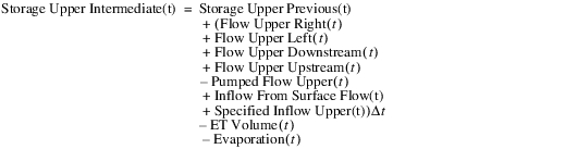
(11.39) 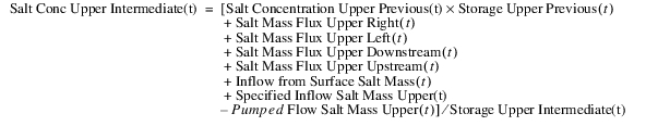
Then, compute the lower-layer intermediate storage and salt concentration as follows:
(11.40) 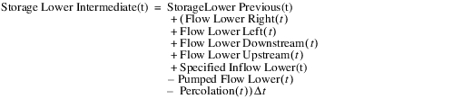
(11.41) 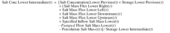
Transfer Water and Salt Up or Down and Compute Layer Concentration
Now that the intermediate storage and salt concentrations have been computed, the method computes how the water and salt transfers between the two layers to maintain a constant thickness of the upper layer. This computation uses the actual storage in each layer and the intermediate values computed previously; see Compute Temporary Storage and Concentration.
If Storage Upper Intermediate(t) >= Storage Upper(t)
Transfer water from the upper to the lower layer
(11.42) 
(11.43) 
(11.44) 
(11.45) 
Else If Storage Upper Intermediate(t) < Storage Upper(t) and Storage Lower Intermediate(t) > 0
If Storage Lower Intermediate(t) >= Storage Upper(t) - Storage Upper Intermediate(t)
(11.46) 
Else
(11.47) 
End If
(11.48) 
(11.49) 
(11.50) 
End If
Finally, as preparation for the next timestep’s dispatch, the previous salt concentrations are set at t plus one.
(11.51) 
(11.52) 
Set Salt Mass and Flux
If the None method is selected in the Show Salt Mass and Flux category, the dispatch method is complete.
Otherwise, when a Show Salt Mass and Flux method is selected, then the salt mass slots are set. There is one agg series slot for each Lateral Link Direction. Each agg series mass slot contains a column for the Total, Upper, and Lower layers. There is also one agg series slot for the object itself. In addition, to Total, Upper, and Lower columns for Salt Mass, it also shows the Salt Mass Flux Upper to Lower. Each column of these agg series slots is set to the appropriate value as computed above.
The Solve 2 Layer Salt dispatch method is complete.
Revised: 08/02/2021