
Groundwater Conductance
Methods in this category allow you to choose how you want to specify conductance.
This category is available when any of the non-default, 15 flow methods in the Lateral Link Direction category is selected. It is also available when Head Based Percolation is selected in the GW Deep Percolation category. That is, it is available for any method that instantiates one of the conductance slots on the groundwater object.
Note: You can not mix use of these two approaches across linked groundwater objects. That is, groundwater objects that are calculating conductance cannot be linked to groundwater objects specifying conductance.
This is the default method and does not instantiate any new slots. You must specify each of the conductance values (Conductance Left, Conductance Right, and so on).
This method allows you to specify hydraulic conductivity and the geometry for each flow component. Then the object uses information on the object and on adjacent objects to determine the conductance in each direction. The calculation uses the following equation to take the geometric mean of conductance:
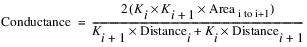
where i is the given object, and i+1 is the connected object. K is the hydraulic conductivity, Areai to i+1 is the area shared by object i and i+1 that is perpendicular to the flow, and Distance is the groundwater’s distance in the direction of the flow.
Slots Specific to This Method
Hydraulic Conductivity
Type: Scalar Slot
Units: Velocity,
Description: This slot contains the hydraulic conductivity, Kx. This represents the conductivity for lateral flows in/out of the groundwater object in the left and right direction.
Information: This value is also used to compute the conductivity in the upstream and downstream directions by dividing by the Anisotropy Ratio.
I/O:
Links: Not linkable
Anisotropy Ratio
Type: Scalar Slot
Units: No Units
Description: This slot contains a ratio, used to adjust the hydraulic conductivity in the upstream/downstream or left/right direction.
Information: This ratio represents the ratio of hydraulic conductivity in Left-Right direction to the Up-Down direction (Kx/Ky). It is applied when computing conductance.
I/O: If not specified, it defaults to 1.0.
Links: Not linkable
Length
Type: Scalar
Units: Length
Description: Length of the groundwater object in the upstream/downstream direction at the centroid. This is considered the Y direction
Information:
I/O: Required input if flow can go left, right, or to deep percolation
Links: Not linkable
Width
Type: Scalar
Units: Length
Description: Length of the groundwater object in the left/right direction at the centroid. This is considered the X direction
Information:
I/O: Required input if flow can go upstream, downstream, or to deep percolation
Links: Not linkable
Thickness
Type: Scalar
Units: Length
Description: Length of the groundwater object in the left/right direction at the centroid. This is considered the Z direction
Information:
I/O: Required input if flow can go left, right, upstream or downstream.
Links: Not linkable
Deep Aquifer Hydraulic Conductivity
Type: Scalar
Units: Velocity
Description: Conductivity to the deep aquifer
Information:
I/O: Required input
Links: Not linkable
Deep Aquifer Depth
Type: Scalar
Units: Length
Description: Distance from the groundwater object to the deep aquifer.
Information: This value is only used to compute conductance
I/O: Required input
Links: Not linkable
Method Details
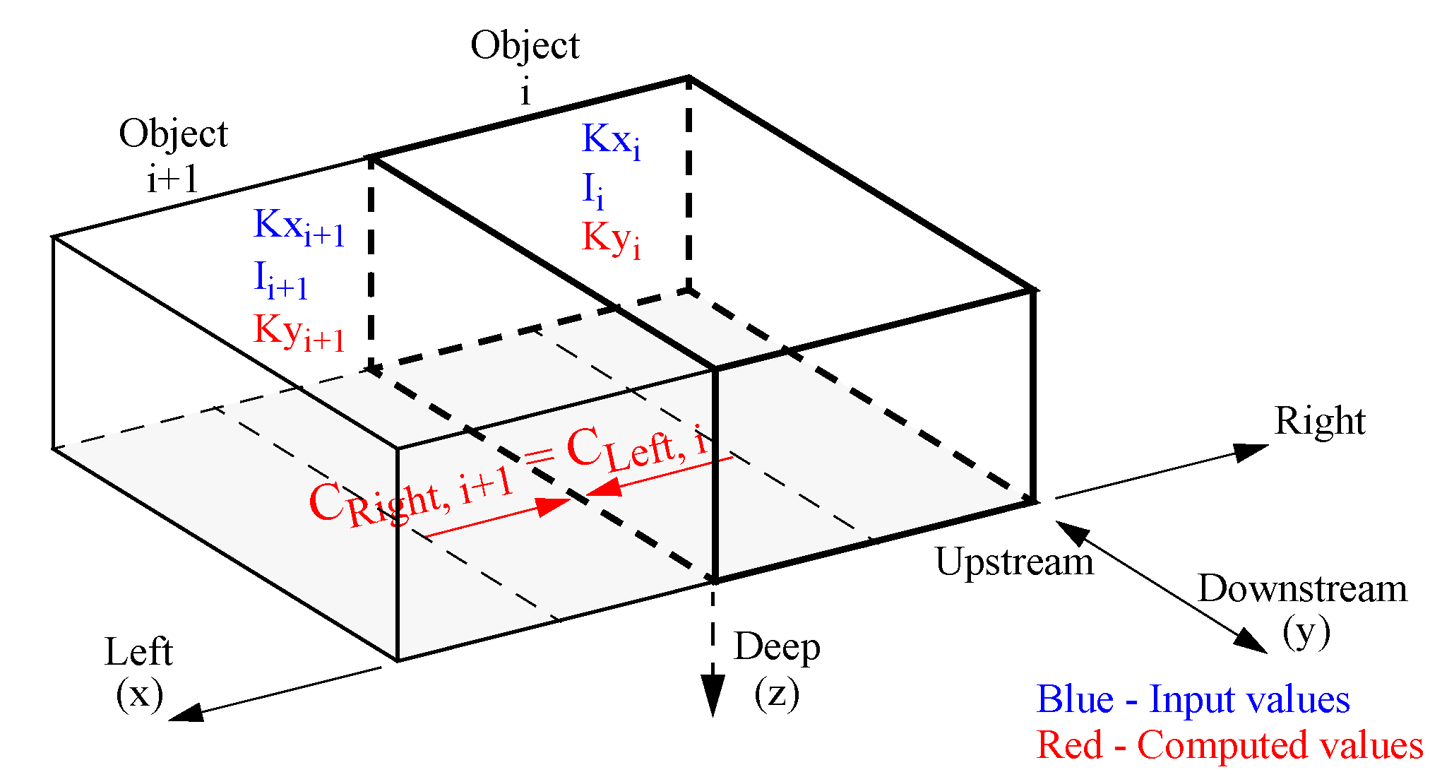
For mass conservation across objects, the Conductance must be identical on adjacent objects; that is, Objecti+1.Conductance Right must equal Objecti.Conductance Left. For the conductance to be identical, the area shared by adjacent objects must be the same.
So that you are not required to specify that the shared area of adjacent objects are the same, the computation averages the areas between adjacent cells. One way to think of this is that the length, width, and thickness are measured/specified at the centroid of the object.
Specifying dimensions at the centroid allows you to input dimensions that are not the same on adjacent objects. This approach does violate the assumption that the cells are rectangular prisms, but in reality, the groundwater objects are rarely rectangular prisms. You can specify the same dimensions on adjacent objects and it will model rectangular prisms.
Figure 15.1
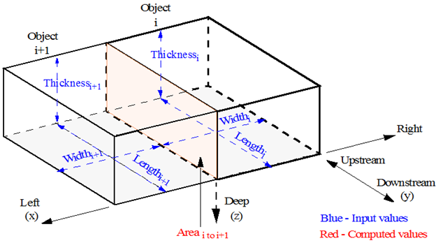
Because the geometry is input, the following assumptions apply:
• Left/Right is perpendicular to the plane defined by Length and Thickness
• Left/Right is in the same plane as the Width.
• Upstream/Downstream is perpendicular to the plane defined by Width
• Upstream/Downstream is perpendicular to the plane as the Length.
• On adjacent objects, Left is connect to Right and vice versa.
• On adjacent objects, Upstream is connected to Downstream and vice versa.
The actual sense of the left/right/upstream/downstream does not matter as long as it is consistent.
Computation Details
The method is executed at the start of the run. If a method is selected (like Deep Percolation) and the appropriate values in the above scalars are missing, an error will be issued and the run will be stopped.
The following process is performed for each groundwater object (computation of conductance in the Left/Right direction is used as an example):
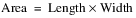
1. Compute the Area as
Note: The Area is registered as having the Length as its Source slot. When a table slot has a source slot, it becomes read-only and displays a cross hatch over the data. It also provides a note indicating the source slot used to compute the data. The source slot is set at beginning of run, so you must initialize the run to see the read-only status.
2. Determine the object (i+1) linked to the Elevation Upstream/Downstream/Left/Right Previous. For example, when it is computing Conductance Left, it will get the slot linked to Elevation Left Previous. From that linked slot, the method will get the parent object and then the appropriate parameters, Thickness, Length, Width, K.
3. Compute the average of the adjacent cell’s dimensions and compute the area shared by the two cells. The area shared between the two cells is the average of their dimensions.

4. The Conductance (C) for each flow component is computed using the information on adjacent objects to compute the conductance values for each direction. This computation takes the harmonic mean of Hydraulic Conductivity (K) according to the following equation (Left/Right is used as an example):
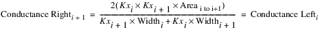
where i is the given object, and i+1 is the connected object. In the equation, Kx is as follows:

Figure 15.2 shows the values input and the computed values for this computation.
Figure 15.2
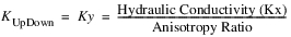
5. This computation is repeated for each side: Upstream (using Ky), Downstream (Ky), and Right (Kx) using the appropriate dimensions. For the upstream and downstream directions, Ky is used, as follows:
6. The deep aquifer conductance is computed as follows:

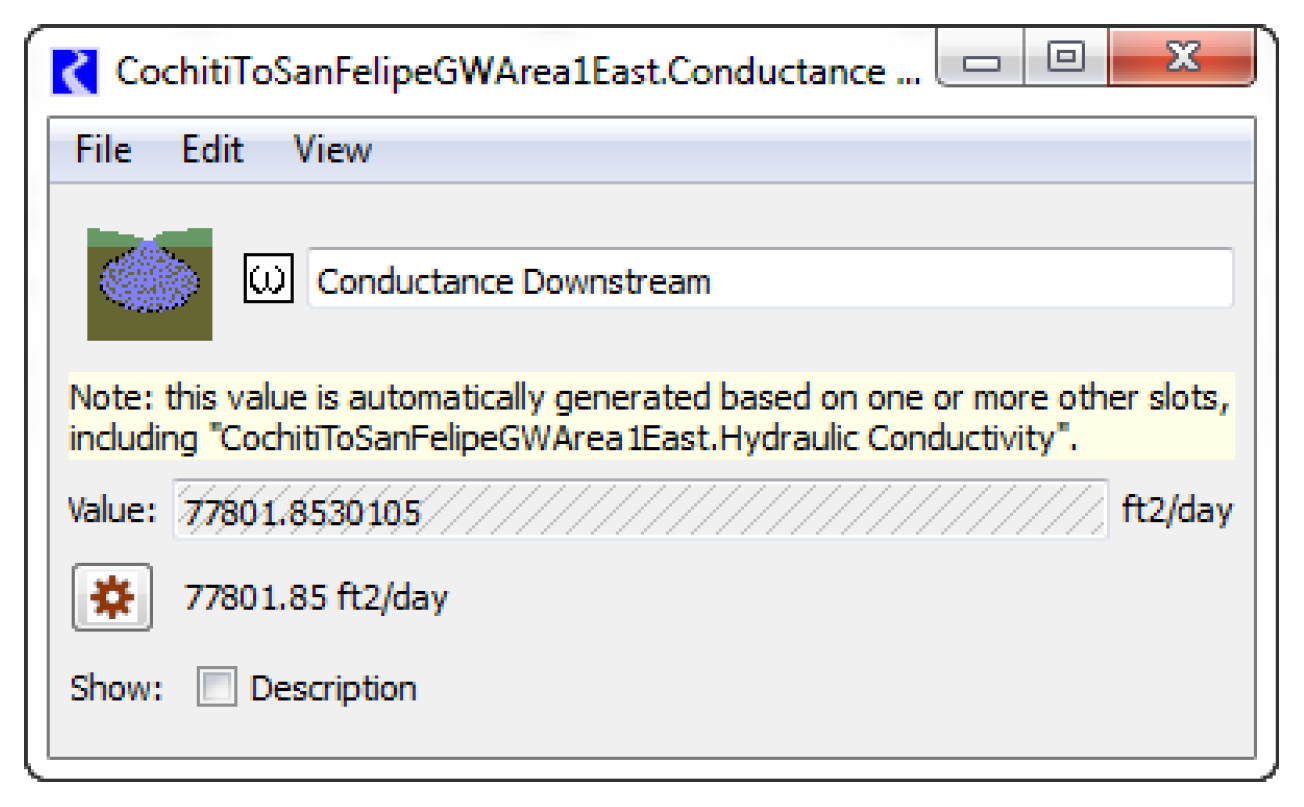
The computed conductances will be set on the appropriate scalar conductance slot. If there are values already on the slot, they will be overwritten.
Note: The appropriate conductance slot(s) will be registered as having a Source slot. When a table slot has a source slot, it becomes read-only and displays a cross hatch over the data. See screenshot below. It also provides a note indicating the source slot used to compute the data. The source slot is set at beginning of run, so you must Initialize the run to see the read-only status. If you deselect this method, you must initialize the run again to clear the source slot.
1 See eqn 2.5.6 in Charbeneau, Randall J, Groundwater Hydraulics and Pollutant Transport, Prentice Hall, 2000.
Revised: 08/02/2021