
Water Quality
Water Quality Overview
Water quality may be modeled in RiverWare along with simulated water quantity calculations. Currently water quality modeling is available on reservoirs, reaches, confluences, bifurcations, canal, gages, aggregate reaches, aggregate diversion site, aggregate distribution canals, water users, and groundwater storage objects. Constituents include Salinity (TDS), Temperature, Dissolved Oxygen (DO), and Total Dissolved Gas (TDG).
The development of the water quality methods were initially completed in 1996, but were not used extensively. They were updated in 2012 to better model salinity but still may require some minor modifications with more extensive testing and use.
Note: In previous versions of RiverWare, the constituents and solution approach were chosen on the run control. You had to choose either Layered/Discretized or Simple Well Mixed. Starting with RiverWare 6.6, this selection is performed on each object. Now, you can mix and match constituents and/or approach within a single model.Use the multi-object method selector to speed the selection process; see “Multiple Object Method Selector” in User Interface for details.
Following is an overview of the available water quality methods.
Layered/Discretized for Salinity, Temperature, and Dissolved Oxygen (DO)
Salinity, Temperature and Dissolved oxygen can be modeled using a layered approach on reservoirs and groundwater objects and a discretized approach on reaches. Other objects pass the constituents along using methods that are indicated with the propagate terminology.
The layered/discretized approach models reservoirs as having two layers, an epilimnion and a hypolimnion. Reaches are modeled based on the selected routing method but can be discretized such that 1 dimensional dispersion can be included. In this approach, mass, concentration, and/or heat are calculated and propagate downstream. As a result, the user should link each constituents mass, concentration, and/or heat slots between objects. For salinity modeling, salt concentrations (instead of mass) should be linked between objects.
Following are features of the Reservoir methods:
• Two-Layer structure with constant epilimnion thickness. Inflows distributed by the user or based on temperature. Outflows are distributed as a cone of influence around the outlet works. The modeling of these distributions are user-selectable methods.
• Segmented two-layer method computes flow vertically and longitudinally through the reservoir. The elevation of the thermocline is assumed to be constant. Inflow and Outflow are distributed based on user-selectable methods. Flow between segments and layers is used to model reservoir salinity.
• Methods for surface heat flux (convection, radiation, evaporation, etc.) and diffusion/dispersion across the thermocline. The complex surface heat flux equations may also be used if evaporation is a component of the mass-balance.
Features of the reach water quality methods include the following:
• Both implicit and explicit control-volume approaches for salinity and temperature, as well as a simple lagged and variable lagging approach.
• Routing methods to support the control-volume methods, including channel characterization schemes and advanced routing algorithms (Muskingum-Cunge, kinematic wave, MacCormack).
• Ability to model the quality of diversions, return flows, local inflows, and seepage.
Features of the Groundwater salinity methods include the following:
• Two-layer structure, with a head based flow solution. The upper layer has a constant structure. Methods are available to see the computed salt mass in addition to salt concentrations.
• Other objects pass constituents downstream so a complex network can be modeled.
Well-mixed Salinity
Salinity can be modeled using simple well mixed methods. These assume that water in each of the objects is completely mixed. In this approach, mass and concentration are calculated.Concentrations propagate upstream or downstream. As a result, the user should link each salt concentrations between objects.
Following are features of the simple well-mixed salt approach:
• On reservoirs, there are user-selectable methods to specify how the reservoir is mixed, either using a weighting factor or using a predictor-corrector algorithm.
• Reaches are well mixed but can only be modeled using the No Routing method. Reaches can model salt contributed or removed through local inflows, diversions, and return flows.
• Confluences, Bifurcations, and Stream Gages pass the Salt upstream or downstream depending on how the object solves
• Agg Diversion Sites and Water Users allow the modeling of return flow salt pickup, i.e. the amount of salt to add to the return flow.
Total Dissolved Gas
High Total Dissolved Gas (TDG) concentrations can reduce the population of some fish species. These effects are most pronounced in the tailwater of reservoirs during spill operations. The TDG concentrations are increased by spills; the turbulent nature of the spill creates air bubbles that are then forced deep into the tailwater. The deep water has higher pressure which cause gases in the bubbles to dissolve in the water. Once dissolved, the gas propagates downstream.
To alleviate the problems of high TDG concentrations, certain reservoir operations are constrained by maximum allowable TDG tailwater concentrations. RiverWare models TDG in both simulation and optimization on the following objects:
• Reservoir objects model TDG of the Spill and Turbine Release. The Spill TDG concentration is a function of the tailwater depth.
• Reach objects propagate the TDG concentration upstream to downstream using simple lagging.
• Within Optimization, methods are available to set up constraints based on TDG information. See “Total Dissolved Gas Methodology” for a description of this approach.
This document describes how to enable and define a water quality simulation. Then the water quality methods and solution approach is presented for each type of object.
How to Use Water Quality
Water quality is modeled by first enabling water quality for the entire system and specifying the timing of the computations, either inline or post process. Select the constituents and methods on each object and populate slots with data. Run the model as usual; the water quality results are stored in slots on the individual objects. Following is a brief description of the steps to set up a water quality model.
Enable Water Quality Modeling
Enable water quality modeling on the Run Control parameters dialog. From Run Control, select either View, then Simulation Run Parameters or View, then Rulebased Simulation Run Parameters, depending on the selected controller. Check the Water Quality box to enable the methods.
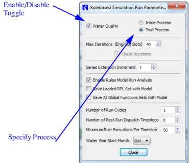
Note: If you later deselect this check box, no water quality solution will occur and the water quality methods will be hidden. The selections and slot are still there, but they are not visible. Select the check box to reenable the water quality solution.
Specify Process
Select one of the Water Quality processes. The following section gives more information on how each process works.
• Inline Process: Water Quality calculations are performed at each timestep inline with the water quantity simulation calculations.
• Post Process: Water Quality calculations for all timesteps are performed at the end of the run, i.e., after all the simulation timesteps have been executed.
How Water Quality Modeling Works
When water quality modeling is enabled and the methods are selected, the water quality slots are instantiated. The water mass balance simulation proceeds as usual with objects dispatching when dispatch conditions are met. Similarly, there are separate dispatch methods for the water quality used to solve how the constituents move through the objects. Water quality dispatch methods are described for each of the objects. Each dispatch method calls a number of utility methods that typically do the work.
Like the mass balance dispatch method, water quality dispatch methods have dispatch conditions. Whenever the water quality dispatch conditions are met for a given method, the object is added to the queue. Water quality dispatch conditions also include water quantity slots. For example, for a reservoir to dispatch for water quality it needs to know Inflow, Outflow, and Storage as well as the inflow salt concentrations, temperature, etc (depending on constituents modeled). The water quality dispatch condition are always solved top down, i.e. after the water balance has been executed for that object. It is not possible to specify or “request” a particular salinity at the lower end of the river and have the system solve for the flow with that salinity. It must first solve for the water quantity, before it can solve for water quality.
The water quality dispatch methods are processed based on the selected process, either Inline or Post, as follows:
• Inline Process: If the Inline Process is selected, at any time dispatch conditions are met, the water quality controller may dispatch object’s water quality dispatch methods. In Inline water quality, there is one dispatch queue that contains both mass balance and water quality dispatch methods. The queue is processed “first in, first out” so mass balance and water quality dispatching may be interspersed.
• Post Process: If the Post Process is selected, water quality dispatching only happens at the end of the run. Two separate queues are maintained, one for mass balance dispatching and one for water quality dispatching. The mass balance queue is processed as usual (at each timestep) while the water quality queue is only processed at the end of the run.
Execution Order
Following is the order of operations for a water quality calculation as part of a regular simulation.
1. Initialization: reset all Output slots to NaN, set Input values, propagate links, and determine first dispatch timestep.
2. Execute Beginning of Run behavior on all objects including Water Quality Beginning of Run checks and evaluation of start of run expression slots.
3. Execute each timestep, as follows:
a. Execute start of timestep expression slots.
b. Execute the Beginning of Timestep on all objects.
c. Execute Timestep: process the dispatch queue until it is empty. If water quality is configured to be an Inline Process, process the water quality dispatch methods when they are on the queue. The queue is first in, first out order.
d. Execute End of Timestep on all objects.
e. Execute end of timestep expression slots.
4. Advance the timestep and repeat the five steps above.
5. Execute End of Run behavior on all objects.
6. If water quality is configured to be Post Process, process the water quality dispatch queue which contains water quality dispatch methods as necessary.
7. Evaluate all end of run expression slots.
Combining water quality with Rulebased Simulation allows the rules to reference water quality slots in making operating decisions. The Inline Process water quality dispatching happens during the timestep when the required dispatch conditions are met. This means that water quality can dispatch multiple times during a timestep based on the values that the rules set and whether the dispatch slots are reset.
In a rulebased simulation run with the Post Process water quality selected, dispatching happens at the end of the run. Rules cannot reference water quality information as it has not been solved yet.
Viewing Water Quality Dispatch Information
The Model Run Analysis tool is used to show dispatching information. See “Simulation” in Debugging and Analysis for a general description. This utility by default shows object dispatching information for the water quantity solution. When Water Quality is enabled as described above, a Water Quality checkbox is shown on the main Model Run Analysis dialog. When checked, the dialog shows dispatch information for the water quality solution. Double clicking on a cell opens the Dispatch Behavior Details dialog. This dialog has an analogous WQ check box. This details dialog shows the required knowns and unknowns for each dispatch method and the known and unknown status of each slot.
Figure 1.1 Model Run Analysis dialog settings to view water quality data
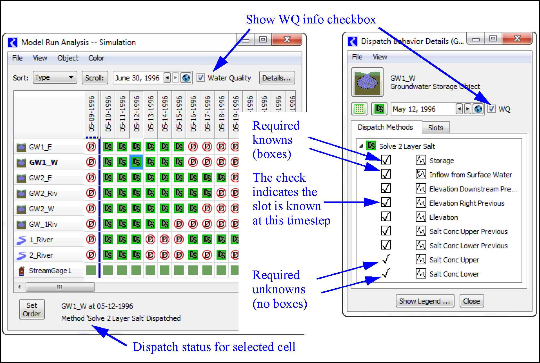
Note: You can also show the details dialog docked in the Model Run Analysis using the Details button.
The Water Quality check boxes represent a single state shared among the Model Run Analysis and all instances of the Dispatch Behaviors Detail dialog; clicking the check box in any of these dialogs also changes the check box in all open dialogs of either type.
Note: When running rulebased simulation and water quality, the model run analysis for water quality only shows the icons indicating dispatch state. There is no analogous Rules Grid for water quality.
Document Organization
The remainder of this document is organized as follows: for each object, we describe the water quality approach including slots and user methods, then present solution and dispatch methods, then utility methods if defined.
Revised: 11/11/2019