
Power
The Power category user methods calculate the flow through the turbines (Turbine Release) and the Power and Energy generated. These methods require that the total Outflow of the Reservoir be known.
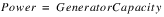
This is the default method in the Power category. It contains no calculations for Power or Energy.
There are no slots specific to this method.
Method Details
1. The method checks that Energy and Turbine Release are not input by the user. These slots cannot be input when None is the selected method. If either of these two slots are input, a RiverWare error is posted and the simulation run terminated.
2. The selected method in the Power Plant Failure category is executed. This sets the Power Plant Cap Fraction, if necessary, and checks for plant shutoff/failure.
3. If the plant is shutoff/failed, the turbine Release is set to 0.0. Otherwise, the Turbine Release is calculated as the difference between Outflow and Spill.
The No Power Turbine Flow method is used to model Turbine Release without any power generation. Turbine Release is calculated as the Outflow minus Spill. The computed Turbine Release can not be larger than the Max Flow Through Turbines.
Slots Specific to This Method
Max Flow Through Turbines
Type: Table Slot
Units: LENGTH vs. FLOW
Description: relationship between Pool Elevation and Turbine Capacity
Information:
I/O: Required input
Links: Not linkable
Method Details
1. The method checks that Energy and Turbine Release are not input by the user. These slots are not valid for user input when the No Power Turbine Flow method is selected. If either of these two slots is input, a RiverWare error will be posted and the simulation run is terminated.
2. Pool Elevation is used in an interpolation scheme to determine the maximum release from the Max Turbine Flow table.
3. The selected method in the Power Plant Failure category is executed. This sets the Power Plant Cap Fraction, if necessary, and checks for plant shutoff/failure.
4. If the plant is shutoff/failed, the turbine Release is set to 0.0. Otherwise, the Turbine Release is set as either Outflow minus Spill or maximum release. It is set as the lesser of the two values because the Turbine Release must be less than the Turbine Capacity.
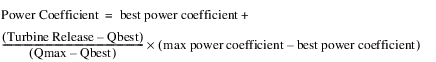
The Plant Power Coefficient method calculates the Power and Energy generated based on the whole plant characteristics. If the Power Coefficient is specified, the Power is calculated directly, unless the BEST EFFICIENCY or MAX CAPACITY flag is set on Energy. If its not input, the Power Coefficient is found from the interpolation of the Best or Max Turbine Q and Power Coefficient tables using the current Operating Head. If the Turbine Release is less than the Best Turbine Q, the Best Power Coefficient Table is used. If the Turbine Release is greater than the Max Turbine Q, then the Max Power Coefficient Table is used. If the Turbine Release is between the two, an intermediate Power Coefficient Value is found by interpolation.
Slots Specific to This Method
Best Hydro Capacity
Type: Series Slot
Units: POWER
Description: most efficient hydro capacity of the plant at the current timestep
Information: Solved iteratively based on Best Turbine Q and the Best Power Coefficient.
I/O: Output only
Links: Not linkable
Best Power Coefficient
Type: Table Slot
Units: LENGTH vs. POWER per FLOW
Description: Operating Head vs. most efficient power coefficient
Information: The Power Coefficient relates turbine release to power generated. The Best Power Coefficient represents the most efficient power generation.
I/O: Required input
Links: Not linkable
Best Turbine Q
Type: Table Slot
Units: LENGTH vs. FLOW
Description: Operating Head vs. flow through turbine for most efficient power generation
Information:
I/O: Required input
Links: Not linkable
Hydro Capacity
Type: Agg Series Slot
Units: POWER
Description: maximum hydro capacity of plant at the current timestep
Information: Solved iteratively based on Max Turbine Q and the Maximum Power Coefficient.
I/O: Output only
Links: Usually not linked
Max Power Coefficient
Type: Table Slot
Units: LENGTH vs. POWER per FLOW
Description: Operating Head vs. maximum power coefficient
Information: The Power Coefficient relates turbine release to power generated. The Max Power Coefficient represents the maximum Turbine Release.
I/O: Required input
Links: Not linkable
Max Turbine Q
Type: Table Slot
Units: LENGTH vs. FLOW
Description: Operating Head vs. maximum flow through the turbine
Information:
I/O: Required input
Links: Not linkable
Minimum Power Elevation
Type: Table Slot
Units: LENGTH
Description: minimum Pool Elevation for power production
Information:
I/O: Required input
Links: Not linkable
Plant Power Limit
Type: Series Slot
Units: POWER
Description: Power output is limited to this value
Information:
I/O: Optional; This constraint on power is only applied if the user inputs a value for the timestep.
Links: Not linkable
Power Coefficient
Type: Series Slot
Units: POWER per FLOW
Description: power generated per unit power release
Information:
I/O: Optional; can be input or calculated.
Links: Usually not linked
Power Plant Cap Fraction
Type: Series Slot
Units: FRACTION
Description: the percentage of full capacity of the turbine units in the hydropower plant
Information:
I/O: Optional; The value of this slot defaults to 100% if not input by user.
Links: Not linkable
Plant Power Table
Type: Table Slot
Units: LENGTH, FLOW, POWER
Description: 3‑D table used to determine power linearization in optimization
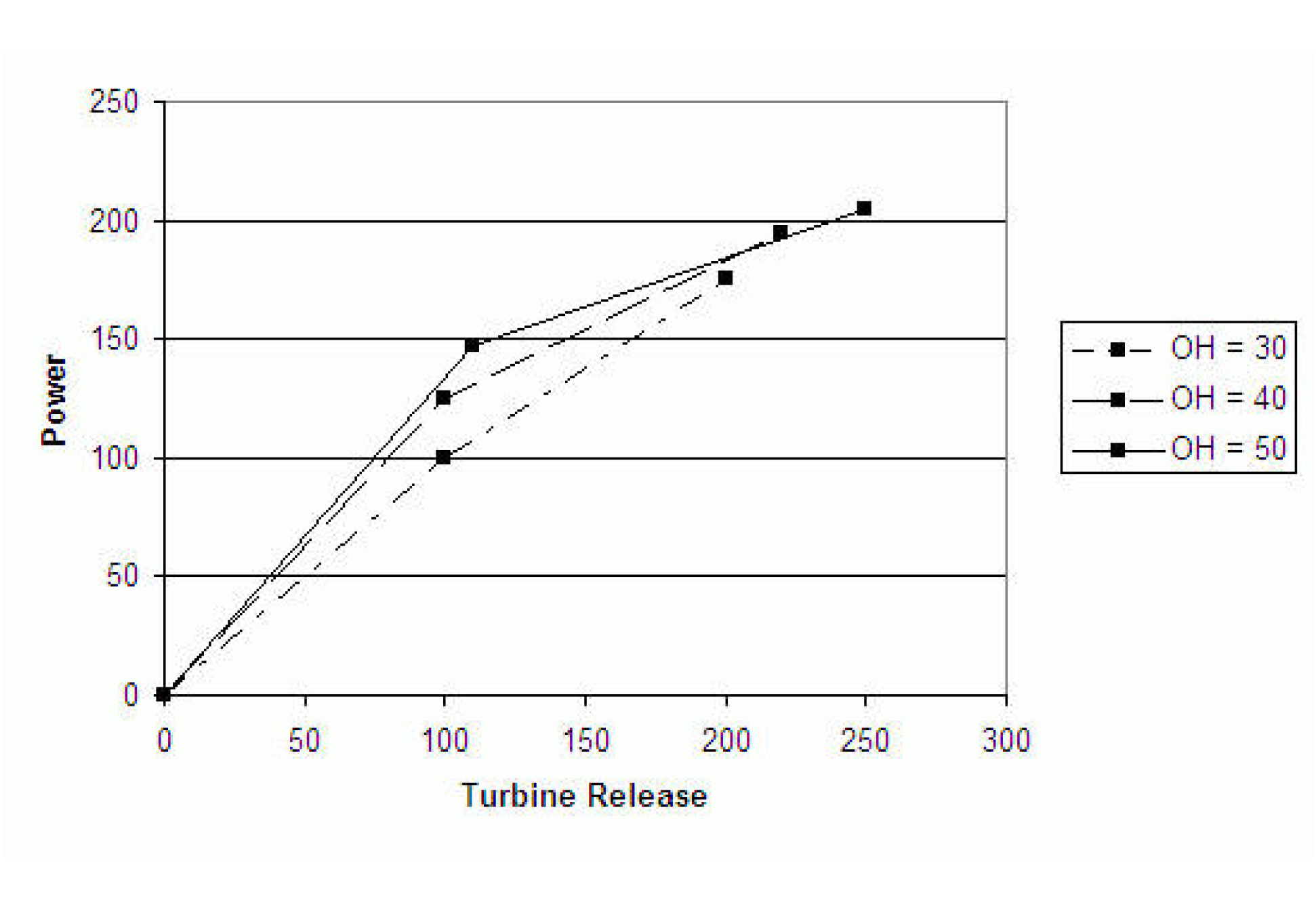
Information: This slot is only used for this method in the context of an Optimization run. It must be populated with data when this method is used in the context of Optimization. It can be left empty otherwise. Data must be entered into the table in increasing, concave blocks of the same Operating Head for the three-dimensional table interpolation to work correctly. For every block of the same Operating Head in column 1, Turbine Release and the corresponding Power should be listed in increasing, concave order in columns 2 and 3. There must be a point of zero Turbine Release and zero Power for each Operating Head. The following table is an example of the proper way to formulate the Plant Power Table. This table can be derived from the Best Turbine Q, Best Power Coefficient, Max Turbine Q and Max Power Coefficient slots.
Operating Head | Turbine Release | Power |
|---|---|---|
30 | 0 | 0 |
30 | 100 | 100 |
30 | 200 | 175 |
40 | 0 | 0 |
40 | 100 | 125 |
40 | 220 | 195 |
50 | 0 | 0 |
50 | 110 | 147 |
50 | 250 | 205 |
I/O: Input Only
Links: Not Linkable
Power Curvature Tolerance
Type: Scalar
Units: None
Description: The power curvature tolerance is used to account for anomalies in Plant Power Table data and round off error while calculating slopes.
Information: This slot is only used in the context of an Optimization run. Although the units for the slot are None, the comparison is implicitly using (MW/cms).
I/O: Input or defaults to 1X10⁻⁶
Links: Not linkable
Method Details
This method performs calculations to compute the power generated at each timestep.
1. Tailwater Elevation and Operating Head are determined based on the user method selected in the Tailwater category.
2. The selected method in the Power Plant Failure category is executed. This method sets the Power Plant Cap Fraction (the default is 1.0) and checks for plant shutoff/failure.
3. The method checks if the Minimum Power Elevation was input by the user. If no value was input, a RiverWare error is posted and the simulation run is terminated. If the previous Pool Elevation is less than the Minimum Power Elevation or the plant has shut off or failed (from the call to the selected Power Plant Failure category method), the following steps are taken.
a. Energy, Power, Hydro Capacity, and Best Hydro Capacity are set equal to zero.
b. If the Turbine Release is input or already set from the dispatch method Solve given Inflow, Release, a RiverWare error is flagged and the run is terminated.
c. Turbine Release is set equal to zero.
4. Operating Head is used to determine the maximum power release through interpolation on the Max Turbine Q table. The maximum power release value is multiplied by the Power Plant Cap Fraction to account for the state of the turbine units.
If Turbine Release is already set from the dispatch method Solve given Inflow, Release, the following checks are performed:
• If Turbine Release is greater than Outflow - Spill, a RiverWare error is posted reading, “Requested Power Release is Greater than Outflow - Spill”, and the run is terminated.
• If Turbine Release is greater than the maximum power release, a RiverWare error is posted reading, “Requested Turbine Release is greater than Maximum Turbine Capacity”, and the run is terminated.
If the Turbine Release was input by the user, a RiverWare error is posted and the run is terminated. If neither the Energy nor the Turbine Release were input and the Energy was not set by a rules, the Turbine Release is set equal to the lesser of the Maximum Power Release or the value of the Outflow minus the Spill.
Using the calculated value of Operating Head, QmaxTemp and QbestTemp are obtained from the Max Turbine Q Table and the Best Turbine Q Table, respectively. Both values are then multiplied by the Power Plant Cap Fraction to obtain Qmax and Qbest. The Operating Head is also used to determine both the best power coefficient and the max power coefficient through interpolation of the Best Power Coefficient and Max Power Coefficient tables, respectively.
The following calculations are not performed if Energy is Input, set by a Rule, or flagged BEST EFFICIENCY or MAX CAPACITY. In these cases the Power, Energy, and Power Coefficient have already been calculated in Plant Power Coefficient Release.
If the Power Coefficient is not input by the user, the following steps are performed.
1. If the maximum power coefficient is greater than the best power coefficient, the following RiverWare error is posted, “best Power Coeff < full gate Power Coeff”, and the simulation run is terminated.
2. If Qbest is greater than Qmax, the following RiverWare error is posted, “Best Turbine Q > Max Turbine Q”, and the simulation run is terminated.
3. If Qbest equals Qmax, the Power Coefficient is set equal to the best power coefficient.
4. If none of the previous three conditions are satisfied and the Turbine Release is less than or equal to Qbest, the Power Coefficient is set equal to the best power coefficient.
5. If none of the previous four conditions are satisfied and the Turbine Release is less than Qmax, the Power Coefficient is calculated using the following equation:
6. If none of the previous four conditions are true, the Power Coefficient is set equal to the max power coefficient.
Power is then calculated using the following equation:

If the user has input the Plant Power Limit, the following steps are taken.
1. If the Power Coefficient is input by the user, Power and Turbine Release may need to be recalculated. If the Power is greater than the Plant Power Limit, Power is set equal to the Plant Power Limit and Turbine Release is recalculated as the Plant Power Limit divided by the Power Coefficient.
2. If the Power Coefficient is not input and the Plant Power Limit is exceeded; the Turbine Release, Power, and Power Coefficient may need to be recalculated. If the Power Coefficient is equal to the best power coefficient, the plant is already operating at best efficiency. Therefore, the Turbine Release is set equal to the Plant Power Limit divided by the Power Coefficient and the rest of the flow is spilled. The Power and Power Coefficient do not need to be recalculated.
If the Power Coefficient is not equal to the best power coefficient, Turbine Release, Power, and the Power Coefficient need to be recalculated. This is done through the following steps.
• Temporary variables are calculated from the following equations:


• If Qlimit is greater than Qmax: the Power Coefficient is set equal to the max power coefficient, Turbine release is set equal to Qmax, and Power is set equal to the power at max.
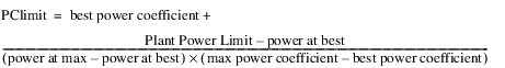
• If Qlimit is less than Qbest: the Power Coefficient is set equal to the best power coefficient, Turbine Release is set equal to Qlimit, and Power is set equal to the Plant Power Limit.
• If Qlimit is less than Qmax but greater than Qbest: the Power Coefficient is set to equal to PClimit, Turbine Release is set equal to Qlimit, and Power is set equal to the Plant Power Limit.
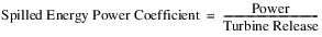
If the Spilled Energy Power Coefficient is visible on the reservoir and it is not input, it is set equal to the Power Coefficient.
Energy is calculated as Power multiplied by the timestep (in hours).
The following calculations always take place, regardless of the flag on Energy.
If either the Turbine Release is equal to the maximum power release or the Energy is at the maximum capacity, Hydro Capacity is set equal to Power and the Best Hydro Capacity is obtained from the getHydroCap function. If the energy is at the Best Efficiency, the Best Hydro Capacity is set equal to the Power and the Hydro Capacity is obtained from the getHydroCapacity function. If neither the Turbine Release is equal to the maximum power release, the Energy is at the maximum capacity, nor the Energy is at the Best Efficiency, both Hydro Capacity and Best Hydro capacity are obtained with the getHydroCap function.
The Plant Efficiency Curve method calculates the Power and Energy generated based on the whole plant characteristics. If the Power Coefficient is specified, the Power is calculated directly, unless the BEST EFFICIENCY or MAX CAPACITY flag is set on Energy. If the Power Coefficient is not input, the Power is found by a 3‑D interpolation of the Plant Power Table using the current, average Operating Head and Turbine Release. The Power Coefficient is calculated as Power divided by Turbine Release.
Slots Specific to This Method
Plant Power Table
Type: Table Slot
Units: LENGTH, FLOW, POWER
Description: 3‑D table used to determine power using interpolation
Information: Data must be entered into the table in increasing, concave blocks of the same Operating Head for the three-dimensional table interpolation to work correctly. For every block of the same Operating Head in column 1, Turbine Release and the corresponding Power should be listed in increasing, concave order in columns 2 and 3. There must be a point of zero Turbine Release and zero Power for each Operating Head. The second to last row for each Operating Head is the point used to populate the Auto Best Turbine Q Table. This point is typically used to represent all units on at best efficiency. (This may not be equivalent to the point for that Operating Head with the highest efficiency, which should only the most efficient unit(s) at their best efficiency and would correspond to the point in the Auto First Turbine Q table.) The last row for each Operating Head is the point of maximum Turbine Release and maximum Power production and is used to populate the Auto Max Turbine Q table. If there are only two rows for a given Operating Head, both the best efficiency and max capacity are equal to the second row. The following table is an example of the proper way to formulate the Plant Power Table, and the following figure displays the increasing concave blocks at each operating head.
Operating Head | Turbine Release | Power |
|---|---|---|
30 | 0 | 0 |
30 | 100 | 100 |
30 | 200 | 175 |
40 | 0 | 0 |
40 | 100 | 125 |
40 | 220 | 195 |
50 | 0 | 0 |
50 | 110 | 147 |
50 | 250 | 205 |
I/O: Input Only
Links: Not Linkable
Power Coefficient
Type: Series Slot
Units: POWER per FLOW
Description: power generated per unit flow release
I/O: Optional; if input, it is used to compute power. Otherwise, power is computed from the Plant Power Table
Links: Not usually linked
Hydro Capacity
Type: Series Slot
Units: POWER
Description: This is the maximum power that can be produced at the current timestep
Information: Solved for iteratively based on the Operating Head and maximum possible release.
I/O: Output Only
Links: Not Linkable
Best Hydro Capacity
Type: Series Slot
Units: POWER
Description: This is the power that would be produced at the most efficient operating point at the current timestep.
Information: Solved for iteratively based on the most efficient operating point and the corresponding release.
I/O: Output Only
Links: Not Linkable
Power Plant Cap Fraction
Type: Series Slot
Units: FRACTION
Description: Must be a number less than or equal to 1. If not input, automatically set to 1.
Information: This is the percentage of full capacity of the turbine units in the hydropower plant. For example, if only half of the turbines are operational (and they are all the same), this value would be 0.5
I/O: Can be input by user. If not, value is set to 1.
Links: Not Linkable
Minimum Power Elevation
Type: Series Slot
Units: LENGTH
Description: The minimum elevation at which the reservoir can still produce power.
I/O: Input Only
Links: Not Linkable
Plant Power Limit
Type: Series Slot
Units: POWER
Description: The max power that the plant can produce at a given timestep.
I/O: Optional, only applies if input by user
Links: Not Linkable
Auto Best Turbine Q
Type: Table Slot
Units: LENGTH vs. FLOW
Description: Operating Head vs. Turbine Release for most efficient power generation for each Operating Head in the Plant Power Table
Information: This table is populated automatically at the beginning of the run based on the Plant Power Table. If there are three or more rows for the given Operating Head in the Plant Power Table, the second to last row for that Operating Head is used. This point is typically used to represent all units on at best efficiency. (This may not be equivalent to the point for that Operating Head with the highest efficiency, which should represent only the most efficient unit(s) at their best efficiency and would correspond to the point in the Auto First Turbine Q table.) If there are only two rows (one non-zero row) for a given Operating Head, the Auto Best Turbine Q, Auto Max Turbine Q and Auto First Turbine Q tables will all use the same point. If there are only three rows for a given Operating Head, the Auto Best Turbine Q and Auto First Turbine Q tables will both use the second point.
I/O: Output only
Links: Not linkable
Auto Max Turbine Q
Type: Table Slot
Units: LENGTH vs. FLOW
Description: Operating Head vs. Turbine Release for maximum turbine capacity for each Operating Head in the Plant Power Table
Information: This table is populated automatically at the beginning of the run based on the Plant Power Table using the last row for each Operating Head in the Plant Power Table. If there are only two rows (one non-zero row) for a given Operating Head, the Auto Best Turbine Q, Auto Max Turbine Q and Auto First Turbine Q tables will all use the same point.
I/O: Output only
Links: Not linkable
Auto First Turbine Q
Type: Table Slot
Units: LENGTH vs. FLOW
Description: Operating Head vs. Turbine Release for the first non-zero point for each Operating Head in the Plant Power Table
Information: This table is populated automatically at the beginning of the run based on the Plant Power Table using the first non-zero row for each Operating Head in the Plant Power Table. If there are only two rows (one non-zero row) for a given Operating Head, the Auto Best Turbine Q, Auto Max Turbine Q and Auto First Turbine Q tables will all use the same point. If there are only three rows for a given Operating Head, the Auto Best Turbine Q and Auto First Turbine Q tables will both use the second point.
I/O: Output only
Links: Not linkable
Power Curvature Tolerance
Type: Scalar
Units: None
Description: The power curvature tolerance is used to account for anomalies in Plant Power Table data and round off error while calculating slopes.
Information: Although the units for the slot are None, the comparison is implicitly using (MW/cms).
I/O: Input or defaults to 1X10⁻⁶
Links: Not linkable
Method Details
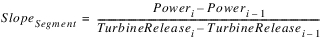
At the start of an optimization run, the Plant Power Table is checked for concavity. The slope of each segment for each block is calculated as follows:
The table is considered concave if:

The table is required to be concave for optimization runs, but not for simulation or rulebased simulation runs.
This method performs calculations to compute the power generated at each timestep.
1. First, Tailwater Elevation and Operating Head are determined based on the user method selected in the Tailwater category.
2. Next, the selected method in the Power Plant Failure category is executed. This method sets the Power Plant Cap Fraction (the default is 1.0) and checks for plant shutoff/failure.
3. Then, the method checks if the Minimum Power Elevation was input by the user. If no value was input, a RiverWare error is posted and the simulation run is terminated. If the previous Pool Elevation is less than the Minimum Power Elevation or the plant has shut off or failed (from the call to the selected Power Plant Failure category method), the following steps are taken.
a. Energy, Power, Hydro Capacity, and Best Hydro Capacity are set equal to zero.
b. If the Turbine Release is input or already set from the dispatch method Solve given Inflow, Release, a RiverWare error is flagged and the run is terminated.
c. Turbine Release is set equal to zero.
Operating Head is used to determine the maximum power release through interpolation on the Plant Power Table. The maximum power release value is multiplied by the Power Plant Cap Fraction to account for the state of the turbine units.
4. If Turbine Release is already set from the dispatch method Solve given Inflow, Release, the following checks are performed:
– If Turbine Release is greater than Outflow–Spill, a RiverWare error is posted reading, “Requested Power Release is Greater than Outflow - Spill”, and the run is terminated.
– If Turbine Release is greater than the maximum power release, a RiverWare error is posted reading, “Requested Turbine Release is greater than Maximum Turbine Capacity”, and the run is terminated.
5. If the Turbine Release was input by the user, a RiverWare error is posted and the run is terminated. If neither the Energy nor the Turbine Release were input and the Energy was not set by a rules, the Turbine Release is set equal to the lesser of the Maximum Power Release or the value of the Outflow minus the Spill.
6. The following calculations are not performed if Energy is Input, set by a Rule, or flagged BEST EFFICIENCY or MAX CAPACITY. In these cases the Power and Energy have already been calculated in Plant Efficiency Curve Release.
7. If the Power Coefficient is input by the user,

8. Otherwise, Power is found directly from the Plant Power Table using the current Operating Head and the Turbine Release from above. The power coefficient is now calculated as follows:

9. If the user has input the Plant Power Limit, the following steps are taken.
a. If the Power Coefficient is input by the user, Power and Turbine Release may need to be recalculated. If the Power is greater than the Plant Power Limit, Power is set equal to the Plant Power Limit and Turbine Release is recalculated as the Plant Power Limit divided by the Power Coefficient.
b. If the Power Coefficient is not input and the Plant Power Limit is exceeded; the Turbine Release, Power, and Power Coefficient need to be recalculated. The Power is set equal to the Plant Power Limit and the Turbine Release is found using 3‑D interpolation of the Plant Power Table. The Power Coefficient is then calculated as Power divided by Turbine Release.
10. Energy is then calculated as Power multiplied by the timestep length.
11. The following calculations always take place, regardless of the flag on Energy.
12. If either the Turbine Release is equal to the maximum power release or the Energy is at the maximum capacity, Hydro Capacity is set equal to Power and the Best Hydro Capacity is computed iteratively. If the energy is at the Best Efficiency, the Best Hydro Capacity is set equal to the Power and the Hydro Capacity is computed iteratively. If the Turbine Release is not equal to the maximum power release, the Energy is not at the maximum capacity, and the Energy is not at the Best Efficiency, both Hydro Capacity and Best Hydro capacity are computed by an iterative algorithm.
Note: If the Power Plant Cap Fraction is input by the user, it is necessary for the Plant Power Table to basically be scaled back to account for the operating points when the turbines are operating at less than 100%. To do this, when Turbine Release is known and Power is to be found using the Plant Power Curve, Turbine Release is divided by the Power Plant Cap Fraction. This point is then found in the Plant Power Curve for the current operating head and the Power is found using 3‑D interpolation. Finally the Power is multiplied by the Power Plant Cap Fraction to get the actual Power produced for the current timestep.
Note: If Power is known, and Turbine release is to be found in the table. Power is multiplied by the Power Plant Cap Fraction and then this point is found in the Plant Power Curve to solve for Turbine Release. Turbine Release is then divided by the Power Plant Cap Fraction to get the actual Turbine Release for the current timestep.
The Plant Power Equation method is used to calculate Power and Energy using the water power equation.
Slots Specific to This Method
Head Loss
Type: Table Slot
Units: length
Description: The head loss water incurs before it reaches the turbines.
Information: The slot is set to zero if not input by the user.
I/O: optional
Links: Not linkable
Minimum Power Elevation
Type: Table Slot
Units: length
Description: Minimum pool elevation at which power can be generated
Information: Single value in a 1x1 table slot
I/O: Required input
Links: Not linkable
Net Head vs Max Turbine Release
Type: Table Slot
Units: length vs. Flow
Description: relationship between the net head and the maximum possible turbine release
Information: Net Head must account for any head loss
I/O: Required input
Links: Not linkable
Net Head vs Plant Efficiency
Type: Table Slot
Units: Length vs None
Description: This table allows you to specify the efficiency as a function of (previous) Net Head.
Information: This table is used only when the Plant Efficiency Value is empty. The Net Head used in this table look up comes from the previous timestep’s operating head.
I/O: Optional Input
Links: Not Linkable
Plant Efficiency Value
Type: Table Slot
Units: none
Description: the decimal percent efficiency at which the plant is operating
Information: Single value in a 1x1 table slot. Plant efficiency should incorporate both generator efficiency and turbine efficiency.
I/O: Optional Input, if specified, it must be between 0 and 1.
Links: Not linkable
Power Plant Cap Fraction
Type: Series Slot
Units: none
Description: decimal fraction of the power capacity at which the plant is operating
Information: Used in the case of outages or reductions in the plant operating capacity.
I/O: Defaults to 1.0 if not input.
Links: Not linkable
Plant Power Limit
Type: Series Slot
Units: Power
Description: The user specified upper limit on power production
Information: If the Plant Power Limit is exceeded, Power is reduced to the Plant Power Limit and the Energy is recalculated. A new Turbine Release are then calculated based on the Plant Power Limit.
I/O: Optional Input or set by a rule.
Method Details
The method first checks whether Energy is either user input or set by rules. If it is, the method finishes successfully and exits; all power calculations were already performed in the Plant Power Equation Release method.
Otherwise, Tailwater Elevation and Operating Head are determined based on the user method selected in the Tailwater category.
Next, the selected method in the Power Plant Failure category is executed. This method sets the Power Plant Cap Fraction (the default is 1.0) and checks for plant shutoff/failure.
Then, the method checks if the Minimum Power Elevation was input by the user. If no value was input, a RiverWare error is posted and the simulation run is terminated. If the previous Pool Elevation is less than the Minimum Power Elevation or the plant has shut off failed (from the call to the selected Power Plant Failure category method), the following steps are taken.
1. Energy and Power are set equal to zero.
2. If the Turbine Release is input or already set from the dispatch method Solve given Inflow, Release, a RiverWare error is flagged and the run is terminated.
3. Turbine Release is set equal to zero.
Once the initial checks are performed, the method calculates Net Head and Turbine Release as follows:

Next, the Max Turbine Release for the current Net Head is interpolated from the Net Head vs. Max Turb Release table.
If there is a valid value in the Plant Efficiency Value slot, that is used for the efficiency. Otherwise, given the net head from the previous timestep (Operating Head at previous timestep minus Head Loss), the efficiency is interpolated from the Net Head vs Efficiency table. The previous Operating Head is used as an approximation so as not to introduce an additional variable in the iteration. As a result, the Tailwater Elevation at the initial timestep must be input. The net head for the initial timestep is the initial Pool Elevation minus the initial Tailwater Elevation minus Head Loss.
The method checks whether Turbine Release is user input or set by a link or a rule. If Turbine Release is known at the dispatch level, the method will check that it is not greater than Outflow minus Spill or the Max Turbine Release given the current Net Head. If either of these are true, an error will be posted and the run will terminate. Otherwise, the known Turbine Release value will be used in the Power calculations. If Turbine Release is not user input or solved for in the dispatch methods, it is calculated as the minimum of the Max Turbine Release (given the current Net Head) and Outflow minus Spill (either unregulated spill or user specified regulated spill):

Note: If Turbine Release is set to MaxTurbineRelease, it means there is still some remaining water that must be passed via regulated spill. This is calculated in the spill calculations. If Turbine Release is set to Outflow minus Spill, it means Spill consists of Unregulated Spill and any input Regulated Spill; all other water passes through the turbines.
Once efficiency, Net Head, and Turbine Release are all known, Power is solved for using the Power Equation:
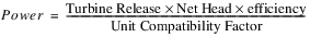
The unit compatibility factor comes from balancing units and is 102.01697767 in internal RiverWare units.
If the computed Power is greater than the Plant Power Limit, the Power is reset to the Plan Power Limit and Turbine Release is recomputed by solving this equation for Turbine Release.
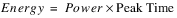
Lastly, Energy is computed as Power multiplied by the time length of the timestep.

The Unit Generator Power method is used to calculate Power and Energy for generating units with individual characteristics. The generating units are grouped by unit type for ease of data entry.
Slots Specific to This Method
Best Generator Flow
Type: Table Slot
Units: length vs. flow
Description: a table for each unit type which gives the relationship between operating head and flow through the generator when operating at best efficiency
Information: There must be a block of data for each unit type given in the Generator Unit Types table. The table is representative of a single unit within the specified unit type.
I/O: Required input
Links: Not linkable
Best Generator Power
Type: Table Slot
Units: length vs. power
Description: a table for each unit type which gives the relationship between operating head and power produced by the generator when operating at best efficiency
Information: There must be a block of data for each unit type given in the Generator Unit Types table. The table is representative of a single unit within the specified unit type.
I/O: Required input
Links: Not linkable
Full Generator Flow
Type: Table Slot
Units: length vs. flow
Description: a table for each unit type which gives the relationship between operating head and flow through the generator when operating at full capacity
Information: There must be a block of data for each unit type given in the Generator Unit Types table. The table is representative of a single unit within the specified unit type.
I/O: Required input
Links: Not linkable
Full Generator Power
Type: Table Slot
Units: length vs. power
Description: a table for each unit type which gives the relationship between operating head and power produced by the generator when operating at full capacity
Information: There must be a block of data for each unit type given in the Generator Unit Types table. The table is representative of a single unit within the specified unit type.
I/O: Required input
Links: Not linkable
Generator Unit Types
Type: Table Slot
Units: NONE
Description: a list of each generating unit and the corresponding unit type
Information: More than one generating unit can be assigned to a given unit type. The unit type must be an integer value beginning with 1 and increasing by increments of 1.
I/O: Required input
Links: Not linkable
Generators Available and Limit
Type: Table Series Slot
Units: fraction and power
Description: a time series specifying the availability and power limit of each generating unit.
Information: Availability is a number between 0 and 1 which represents the percentage of the timestep that the unit is available. There must be a block of data for each row in the Generator Unit Types table. The Power Limit has no effect on the flow through the turbines.
I/O: Required input
Links: Not linkable
Hydro Capacity
Type: Agg Series Slot
Units: power
Description: the maximum power production possible at the current timestep
Information: This value is the sum of all generators operating at full capacity for the given operating head at the current timestep.
I/O: Output only
Links: Could be linked to a Data Object, but usually not linked.
Minimum Power Elevation
Type: Table Slot
Units: length
Description: the minimum pool elevation required for power production
Information: When the Pool Elevation drops below this value, a warning is posted and no power is produced.
I/O: Required input
Links: Not linkable
Power Coefficient
Type: Series Slot
Units: power/flow
Description: power generated per unit power release
Information: This coefficient corresponds to the efficiency of the entire plant. It is not used in calculation and is displayed only for the benefit of the user.
I/O: Output only
Links: Could be linked to a Data Object, but usually not linked.
Method Details
The Unit Generator Power method begins by computing the availability and power limits of each unit type. Availability and power limit values are computed as the sum of the values from the availability and power limit columns, respectively, in the Generators Available and Limit slot. A value for availability and power limit is computed for each unit type.
First, Tailwater Elevation and Operating Head are determined based on the user method selected in the Tailwater category.
Next, the selected method in the Power Plant Failure category is executed. This method sets the Power Plant Cap Fraction if necessary (the default is 1.0) and checks for plant shutoff/failure.
If the plant has shut off or failed (from the call to the selected Power Plant Failure category method), the following steps are taken.
1. Energy and Power are set equal to zero.
2. If the Turbine Release is input or already set from the dispatch method Solve given Inflow, Release, a RiverWare error is flagged and the run is terminated.
3. Turbine Release is set equal to zero.
Then the efficiency of each unit type is calculated by the following equation:
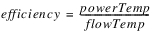
PowerTemp and flowTemp, both local variables, are computed from the Best Generator Power and Best Generator Flow tables, respectively, using the current Operating Head. Each unit type is then sorted in descending order based on the computed efficiency.
Turbine Release has already been computed by the dispatch method and the power produced from the known Turbine Release must be calculated. The method begins to add entire unit types (operating according to the best flow and power tables and beginning with the most efficient type) until the Turbine Release is exceed or all the unit types have been added. If the power generated by a particular unit type exceeds the power limit for that unit type, the power produced from that type is set to the power limit. The power limit has no effect on the flow going through the turbines. If the Turbine Release is exceeded, the last generator type is interpolated to compute the Power exactly (see equation below). However, if all the unit types have been added and the Turbine Release cannot be met, the method assumes all unit types are operating at full capacity (according to the Full Generator Flow and Full Generator Power tables). Then if the Turbine Release is exceeded, the last generator type added is interpolated to compute the Power exactly (see equation below). However, if the Turbine Release still cannot be met, all unit types are run at full capacity. Turbine Release is reset to the maximum flow through the turbines and Power is set as the maximum power produced by the turbines (at the given operating head). The spill must be recalculated to handle the excess Turbine Release that could not be met.
The interpolation equation used to calculate Power is given below:
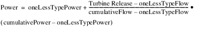
where oneLessTypePower is the power produced from all the previous types added (excluding the most recent type added); oneLessTypeFlow is the flow through all the previous unit types (excluding the most recent type added); cumulativePower is the power produced from all the unit types added (including the most recent type); and cumulativeFlow is the flow through all the unit types added (including the most recent type).
Note: This equation assumes the relationship between power and flow is linear, regardless of the actual relationship specified in the power and flow tables. It is also interpolating over an entire type of generators.
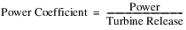
The Power Coefficient is then calculated by the following equation:
If all the unit types were added, the Spilled Energy Power Coefficient is equal to the Power Coefficient. However, if all the types were not added, the Spilled Energy Power Coefficient is set equal to the efficiency of the last type added.
Energy is calculated as the product of the Power and the timestep length. Hydro Capacity is set as the power produced from all units operating at full capacity.
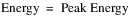
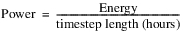
The Peak and Base method computes the Power and Energy generated by the entire plant based on the fraction of each timestep operated at peak flow and base flow. It is a long timestep method, modeled after the U. S. Bureau of Reclamation’s CRSS peak-base power calculation. A peaking flow value is first determined from the Outflow, Tailwater Elevation and Best Generator Flow. A minimum Base Flow and Power production are assumed for the entire timestep. Next, the number of hours to operate at peak power is calculated from the remaining volume of water released during that timestep. Peak production and base production are then added to determine the total Energy. Power is calculated by dividing the Energy by the timestep length in hours. Power Capacity is the power that could be generated if the flow is directed through the turbine(s) given an operating head. This is added to distinguish between actual power production and the power that could be produced.
Slots Specific to This Method
Base Flow
Type: Series Slot
Units: FLOW
Description: minimum flow through turbines to produce energy
Information: If this value is not input or set by a rule, the value is set from the Base Flow Table.
I/O: Input, Output or set by a Rule
Links: Linkable
Base Flow Table
Type: Table Slot
Units: FLOW vs. FLOW
Description: Outflow from the Reservoir vs. base flow
Information: This table gives the minimum flow required through the turbines as a function of the average total outflow from the Reservoir.
I/O: Required input
Links: Not linkable
Base Power
Type: Series Slot
Units: Power
Description: Power produced during base flow operations
Information:
I/O: Optional input or set by a rule. If not input or set by a rule, then this value will be set to the value in the Off Peak Capacity table slot.
Links: Linkable
Best Generator Flow
Type: Table Slot
Units: LENGTH vs. FLOW
Description: Operating Head vs. flow through the turbine at best efficiency
Information: The minimum and maximum values of operating head in this table are used as limiting values. The operating head is reset to the minimum or maximum in this table if it exceeds these constraints. This slot gets used by multiple Power methods. For the Peak Power method, all units are assumed to have the same Best Generator Flow. If there are columns in this slot for multiple unit types, only the columns for unit type 1 (first two columns) will be used. The other columns will be ignored.
I/O: Required input
Links: Not linkable
Best Generator Power
Type: Table Slot
Units: LENGTH vs. POWER
Description: Operating Head vs. power at best efficiency
Information: Power produced by the entire plant at base energy flow. This slot gets used by multiple Power methods. For the Peak Power method, all units are assumed to have the same Best Generator Power. If there are columns in this slot for multiple unit types, only the columns for unit type 1 (first two columns) will be used. The other columns will be ignored
I/O: Required input
Links: Not linkable
Maximum Turbine Power
Type: Table Slot
Units: POWER
Description: maximum turbine power output
Information:
I/O: Required input
Links: Not linkable
Min and Max Operating Head
Type: Table Slot
Units: LENGTH
Description: The minimum and maximum operating head for the turbines
Information:
I/O: Required input
Links: Not linkable
Number of Units
Type: Table Slot
Units: NONE
Description: Integer number of turbines in plant
Information:
I/O: Required input
Links: Not linkable
Off Peak Capacity
Type: Table Slot
Units: POWER
Description: The default constant power produced during base flow operations
Information: The value in the table slot is used for base power operations if the Base Power is not input or set by a rule.
I/O: Required input
Links: Not linkable
Peak Flow
Type: Series Slot
Units: FLOW
Description: The most efficient flow through turbines for the current Operating Head
Information: This slot represents the total plant peak flow.
I/O: Output only
Links: Not linkable
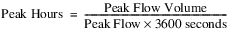
Peak Hours
Type: Series Slot
Units: TIME
Description: The number of hours operated at peak flow
Information:
I/O: Output only
Links: Not linkable
Plant Efficiency
Type: Series Slot
Units: FRACTION
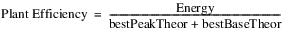
Description: The ratio of actual power produced to peak and base theoretical power
Information:
I/O: Output only
Links: Not linkable
Power Capacity
Type: Agg Series Slot
Units: POWER
Description: The power that could be produced if flow is directed through the turbines given the operating head.
Information:
I/O: Output only
Links: Not linkable
Power Plant Cap Fraction
Type: Series Slot
Units: FRACTION
Description: the percentage of full capacity of the turbine units in the hydropower plant
Information: The value of this slot defaults to 100% if not input by user.
I/O: Optional input
Links: Not linkable
Method Details
The method proceeds as follows:
Check for Plant Failure
First, the selected method in the Power Plant Failure category is executed. This method sets the Power Plant Cap Fraction if necessary (the default is 1.0) and checks for plant shutoff/failure.
If the plant has shut off or failed (from the call to the selected Power Plant Failure category method), the following steps are taken.
1. Energy, Power, Base Flow, Peak Flow, Peak Power, Power Capacity, and Plant Efficiency are set equal to zero.
2. If the Turbine Release is input or already set from the dispatch method Solve given Inflow, Release, a RiverWare error is flagged and the run is terminated.
3. Turbine Release is set equal to zero.
4. Tailwater and Operating Head are computed and set. No further computations are performed.
Check for Input Energy or Turbine Release
If either the Energy or Turbine Release is input by the user, a RiverWare error is posted and the simulation run is terminated. These are not valid input slots for the Peak and Base method.
Compute Peak Flow and Peak Power
Peak Flow and Peak Power are then calculated as follows.
1. If either the Maximum Turbine Power is not valid or it is less than 0.00000001 MW, a RiverWare Error is flagged and the simulation run is terminated.
2. The Maximum Turbine Power is then used with the Best Generator Power table to obtain a value for the local variable, headAtMaxPower.
3. headAtMaxPower is used with the Best Generator Flow table to obtain a value for the local variable, flowAtMaxPower. The local variable, TempUnitPeakFlow is initially set equal to flowAtMaxPower.
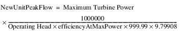
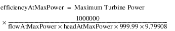
4. The local variable, efficiencyAtMaxPower is calculated by the following formula:

where 999.99 is the density of water (Kg/M3) at five degrees C and 9.79908 is gravitational acceleration (M/s2) at 37 degrees North latitude.
5. The method then iterates until one of the following criteria are met:
– The absolute difference between Qnew and flow is less than 5 cfs.
– The number of iterations is greater than the Maximum Iterations table slot value.
– The Operating Head is less than the Minimum Operating Head.
The following calculations and evaluations are inside the iterative loop.
– The local variable, TempUnitPeakFlow is set equal to NewUnitPeakFlow from the previous iteration.
– The local variable, plantFlow is determined using the following equation:

– The user selected Tailwater calculation is performed using plantFlow
– The updated Operating Head is calculated
– If the Operating Head is greater than the Maximum Operating Head, Operating Head is set equal to the maximum Operating Head
– If the Operating Head is less than the Minimum Operating Head, Operating Head is set equal to the Minimum Operating Head
– If the Operating Head is greater than the headAtMaxPower, the NewUnitPeakFlow is calculated using the following equation:
– If the Operating Head is less than the Maximum Operating Head, greater than the Minimum Operating Head, and less than the headAtMaxPower, NewUnitPeakFlow is obtained from the Best Generator Flow table and the Operating Head.
This set of calculations is repeated until one iteration criterion is met.
6. If Operating head is less than the Minimum Operating Head; Turbine Release, Energy, Power, Power Capacity, Peak Flow, Peak Hours, and flow are all set to zero. Then the Tailwater method is re-executed.
7. If Operating Head is greater than the minimum Operating Head and the headAtMaxPower, UnitPeakPower is set equal to Maximum Turbine Power.
8. If the Operating Head is greater than the Minimum Operating Head and less than the headAtMaxPower, NewUnitPeakFlow was determined from the Best Generator Power table using Operating Head in the iteration.
If Outflow minus Unregulated Spill is greater than the product of NewUnitPeakFlow, Number of Units, and Power Plant Cap Fraction; the following steps are taken.
1. The Tailwater method selected by the user is executed.
2. The Operating Head is calculated.
3. The local variable, headAtMaxPower, is obtained from the Best Generator Power table using the Maximum Turbine Power.
4. The local variable, flowAtMaxPower, is obtained from the Best Generator Flow table using the headAtMaxPower.
5. The local variable, efficiencyAtMaxPower, is computed using the following formula:

6. If Operating Head is greater than headAtMaxPower, NewUnitPeakFlow and UnitPeakPower are calculated using the following equations:


7. If the Operating Head is less than or equal to the headAtMaxPower, NewUnitPeakFlow and UnitPeakPower are determined using the Operating Head in conjunction with the Best Generator Flow and Best Generator Power tables, respectively.
The Peak Flow slot represents the flow through the entire power plant. Therefore, the value in this slot is calculated as NewUnitPeakFlow times Number of Units times Power Plant Cap Fraction. In the calculations that follow, Peak Flow represents the slot value just calculated. Peak Power is calculated as UnitPeakPower times Number of Units times Power Plant Cap Fraction.
Check Base Power and Base Flow
Base Power and Base Flow are determined next. If not input or set by a rule, Base Power is set equal to Off Peak Capacity. If not input or set by a rule, Base Flow is determined by looking up Outflow on the Base Flow Table. It is a lookup, not an interpolation.
Compute Peak and Base Hours
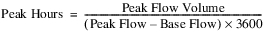
The number of hours required to operate at base and peak flows are computed next using the following equations:


If Peak Hours is greater than the length of the timestep; Peak Hours is set equal to the timestep, Base Hours are set to zero, Turbine Release is set to Peak Flow, and Total Controlled Release is calculated as Outflow minus Unregulated Spill. If Peak Hours is less than or equal to the length of the timestep, Peak Hours and Base Hours remain as calculated by these formulas, Turbine Release is Outflow minus Spill, and Total Controlled Release is set equal to the Peak Flow.
Compute Theoretical and Actual Energy
The theoretical and actual energy production are computed next. The local variable, peakEnergy is calculated as Peak Hours times Plant Peak Power. The local variable, baseEnergy is calculated as Base Hours times Base Power.
The local variable, bestBaseTheor (representing the theoretical, most efficient base energy) is calculated using the following equation:

The local variable bestPeakTheor (representing the theoretical most efficient peak energy) is calculated using the following equation:

The value, 0.00980229, is a conversion factor necessary for energy to have units of megawatt-hours.

For Q in cms and Head in meters the final conversion is 0.00980229.
Set the slots
Finally, the following slots are set:


If a spill method is selected which utilizes the Spilled Energy Power Coefficient and this value is not input by the user, it is set as follows:

If Turbine Release is zero, the Spilled Energy Power Coefficient is also zero.
Note: With this Power method, the Tailwater Elevation and Operating Head slot values that are reported are calculated using the Total Controlled Release, not the average Outflow over the timestep as is used with most methods. Total Controlled Release is the Peak Flow when Peak Hours are less than the timestep. Otherwise it is the Outflow minus Unregulated Spill. This is the way that Tailwater Elevation and Operating Head were reported in the U.S. Bureau of Reclamation’s original CRSS peak and base power calculation on which this method is based. Within the method, the calculation of Peak Power and Base Power use their own Tailwater Elevation and Operating Head calculations based on the appropriate corresponding flows.
The Peak Power method is similar to the Peak and Base method except that it computes power and energy based on Peak Flow only. A peaking flow value is first determined from the Outflow, Tailwater Elevation, and Best Generator Flow. The number of hours to operate at peak power is then calculated from the volume of water released during that timestep. A distinction is made between actual power production and the power that could be produced. Power Capacity is the peak power capacity. Power is calculated by dividing the energy by the timestep length in hours. There is no Base Flow power production.
Slots Specific to This Method
Best Generator Flow
Type: Table Slot
Units: LENGTH vs. FLOW
Description: operating head vs. flow through the turbine at best efficiency
Information: The minimum and maximum values of operating head in this table are used as limiting values. The operating head is reset to the minimum or maximum in this table if it exceeds these constraints. This slot gets used by multiple Power methods. For the Peak Power method, all units are assumed to have the same Best Generator Flow. If there are columns in this slot for multiple unit types, only the columns for unit type 1 (first two columns) will be used. The other columns will be ignored.
I/O: Required input
Links: Not linkable
Best Generator Power
Type: Table Slot
Units: LENGTH vs. POWER
Description: operating head vs. power at best efficiency
Information: This slot gets used by multiple Power methods. For the Peak Power method, all units are assumed to have the same Best Generator Power. If there are columns in this slot for multiple unit types, only the columns for unit type 1 (first two columns) will be used. The other columns will be ignored.
I/O: Required input
Links: Not linkable
Generator Efficiency
Type: Table Slot
Units: FRACTION
Description: the efficiency of the generators in producing power
Information: This value is the fraction of the maximum theoretical power which could be obtained from an ideal turbine.
I/O: Required input
Links: Not linkable
Maximum Turbine Power
Type: Table Slot
Units: POWER
Description: maximum turbine power output
Information:
I/O: Required input
Links: Not linkable
Min and Max Operating Head
Type: Table Slot
Units: LENGTH
Description: the minimum and maximum operating head for the turbines
Information:
I/O: Required input
Links: Not linkable
Number of Units
Type: Table Slot
Units: NONE
Description: integer number of turbines in plant
Information:
I/O: Required input
Links: Not linkable
Peak Flow
Type: Series Slot
Units: FLOW
Description: most efficient flow through turbines for the current Operating Head
Information:
I/O: Output only
Links: Not linkable
Peak Hours
Type: Series Slot
Units: TIME
Description: the number of hours operated at peak flow
Information:
I/O: Output only
Links: Not linkable
Plant Efficiency
Type: Series Slot
Units: FRACTION
Description: ratio of actual power produced to peak and base theoretical power
Information:
I/O: Output only
Links: Not linkable
Power Capacity
Type: Agg Series Slot
Units: POWER
Description: power that could be produced if flow is directed through the turbines given the operating head
Information: Calculated by the two peak power methods and cannot be input by the user.
I/O: Output only
Links: Not linkable
Power Plant Cap Fraction
Type: Series Slot
Units: FRACTION
Description: the percentage of full capacity of the turbine units in the hydropower plant
Information: The value of this slot defaults to 100% if not input by user.
I/O: Optional input
Links: Not linkable
Method Details
First, the selected method in the Power Plant Failure category is executed. This method sets the Power Plant Cap Fraction if necessary (the default is 1.0) and checks for plant shutoff/failure.
If the plant has shut off or failed (from the call to the selected Power Plant Failure category method), the following steps are taken.
1. Energy, Power, Peak Flow, Peak Hours, Power Capacity, and Plant Efficiency are set equal to zero.
2. Turbine Release is set equal to zero.
3. Tailwater and Operating Head are computed and set. No further computations are performed.
If Energy or Turbine Release are input by the user, an error is posted. These are not valid input slots for the Peak Power method.
Peak Flow and Peak Power are then calculated as follows.
1. The Maximum Turbine Power is used in the Best Generator Power table to interpolate a value for headAtMaxPower.
2. headAtMaxPower is used in the Best Generator Flow table to interpolate a value for flowAtMaxPower. The local variable TempUnitPeakFlow is temporarily set as flowAtMaxPower.
3. efficiencyAtMaxPower is calculated by the following formula:
where 999.99 is the density of water (Kg/M3) at five degrees C and 9.79908 is gravitational acceleration (M/s2) at 37 degrees North latitude.
4. RiverWare then iterates until one of the following criteria are met
– The absolute difference between NewUnitPeakFlow and TempUnitPeakFlow is less than 5 cfs,
– The number of iterations is greater than the Max Iterations table slot value
– The Operating Head is less than the Minimum Operating Head.
The following calculations and evaluations are inside the iterative loop.
– TempUnitPeakFlow is set equal to NewUnitPeakFlow from the previous iteration.
– plantFlow is calculated using the following equation:
– The selected Tailwater method is executed using plantFlow.
– The updated Operating Head is calculated.
– If the Operating Head is greater than the Maximum Operating Head, the Operating Head is set equal to the Maximum Operating Head.
– If the Operating Head is less than the Minimum Operating Head, Operating Head is set equal to Minimum Operating Head.
– If the Operating Head is greater than headAtMaxPower, NewUnitPeakFlow is calculated as follows:

– If the Operating Head is less than the Maximum Operating Head, greater than the Minimum Operating Head, and less than the headAtMaxPower, NewUnitPeakFlow is obtained from the Best Generator Flow table and the Operating Head.
This set of calculations is repeated until one iteration criterion is met.
5. If Operating head is less than the Minimum Operating Head, Turbine Release, Energy, Power, Power Capacity, Peak Flow, Peak Hours, and flow are all set to zero. Then, the Tailwater method is re-executed. If Operating Head is greater than headAtMaxPower, Peak Power is set equal to Maximum Turbine Power. Otherwise, Peak Power is determined from the Best Generator Power table using Operating Head.
6. Once flow and Peak Power are determined, the following computations are performed:


7. If the value of Peak Hours is greater than the length of the timestep, Peak Hours is set to the length of the timestep, Turbine Release is equal to Peak Flow, and Total Controlled Release is equal to Outflow minus Unregulated Spill. Otherwise, Peak Hours remains unchanged, Turbine Release equals Outflow minus spill, and Total Controlled Release equals Peak Flow.
8. The theoretical and actual energy production is calculated.


The value, 0.00980229, is a conversion factor necessary for energy to have units of megawatt-hours.

For Q in cms and Head in meters the final conversion is 0.00980229.
9. Finally, the following slots are set:

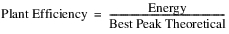
10. If Best Peak Theoretical is equal to zero, Plant Efficiency is also equal to zero. Otherwise Plant Efficiency is calculated as follows:
11. If a spill method is selected which utilizes the Spilled Energy Power Coefficient and this value is not input by the user, it is set as follows:
If Turbine Release is zero, the Spilled Energy Power Coefficient is also zero.
The Peak Power Equation method provides a standard equation method of calculating plant peaking power for a portion of the computational timestep using the water power equation.
Slots Specific to This Method
Head Loss
Type: Table Slot
Units: length
Description: The head loss water incurs before it reaches the turbines.
Information: The slot is set to zero if not input by the user.
I/O: optional
Links: Not linkable
Min Power Elevation
Type: Table Slot
Units: length
Description: Minimum pool elevation at which power can be generated
Information: Single value in a 1x1 table slot
I/O: Required input
Links: Not linkable
Net Head vs. Peak Release
Type: Table Slot
Units: length vs. Flow
Description: relationship between the net head and the maximum possible turbine release
Information: Net Head must account for any head loss
I/O: Required input
Links: Not linkable
Peak Release
Type: Series Slot
Units: FLOW
Description: The flow through the turbines when the plant is operating at peak capacity
Information: Peak Release is solved for iteratively using net head, tailwater elevation and pool elevation
I/O: Output only
Links: Not linkable
Peak Times
Type: Series Slot
Units: TIME
Description: The time at which the plant is operating at peak capacity
Information: Peak Time is calculated as the timestep flow volume divided by the Peak Release.
I/O: Output
Links: Not linkable
Plant Efficiency
Type: Table Slot
Units: none
Description: the decimal percent efficiency at which the plant is operating
Information: Single value in a 1x1 table slot. Plant efficiency should incorporate both generator efficiency and turbine efficiency.
I/O: Defaults to 1.0 if not input. Must be between 0 and 1.
Links: Not linkable
Power Plant Cap Fraction
Type: Series Slot
Units: none
Description: decimal fraction of the power capacity at which the plant is operating
Information: Used in the case of outages or reductions in the plant operating capacity.
I/O: Defaults to 1.0 if not user input. Must be between 0 and 1.
Links: Not linkable
Method Details
The Peak Power Equation method first performs a series of checks.
The selected method in the Power Plant Failure category is executed. This method sets the Power Plant Cap Fraction (the default is 1.0) and checks for plant shutoff/failure.
Then, the method checks if the Minimum Power Elevation was input by the user. If no value was input, a RiverWare error is posted and the simulation run is terminated. If the previous Pool Elevation is less than the Minimum Power Elevation or the plant has shut off or failed (from the call to the selected Power Plant Failure category method), the following steps are taken.
1. Power, Energy, Peak Release, and Peak Time are set equal to zero.
2. If the Turbine Release is input or already set from the dispatch method Solve given Inflow, Release, a RiverWare error is flagged and the run is terminated.
3. Turbine Release is set equal to zero.
4. Tailwater and operating head are computed. No further calculations are performed.
The method checks whether Turbine Release (the average flow through the turbines over the whole timestep) is user input or set by rules; that is, the method checks if the dispatch type is Solve given Inflow, Release. If the given Turbine Release value is greater than Outflow minus Spill, an error is posted and the run is terminated.
If Turbine Release is not user input or set by rules, it is calculated as the minimum of MaxTurbine Release and Outflow minus Spill,

where the Max Turbine Release is interpolated from the Peak Release vs. Net Head Table, given the Net Head over the entire timestep.
In order to calculate the time at peak production, the flow which passes through the turbines during this time period must be calculated. This Peak Release is the maximum possible flow through the turbines given the Net Head and will be solved for iteratively as described in the steps below.
1. Peak Release is initially set to zero.
2. Tailwater Elevation is determined using Peak Release + Spill as the flow value in the selected Tailwater method. If the Turbine Release slot is linked, it can be assumed that Spill is sent elsewhere and does not affect Tailwater so the “flow” value should be set to Peak Release only.
3. The operating head is calculated as the Pool Elevation minus the Tailwater Elevation.
4. The Net Head is calculated as the operating head minus the head loss.
5. Given the Net Head, the Peak Release is interpolated from the Net Head vs. Peak Release table and then multiplied by the Power Plant Cap Fraction.
6. The new Peak Release value is compared with the previous value and the iteration will continue until the value converges.
Note: Convergence Percentage is a general slot on power reservoirs representing the convergence in all iterative solutions; the slot defaults to 0.0001 if not input.
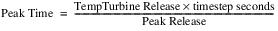
Once Peak Release is calculated, the Peak Time will be solved for as the volume of flow that passes through the turbines in a timestep divided by the Peak Release:
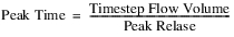
where timestepFlowVolume is an internal variable defined as follows:

RiverWare checks that the Peak Time is not greater than the timestep length. If it is, the run terminates and an error is posted.
Power is calculated with the standard water power equation. The Peak Power Equation method uses Peak Release as the flow value and Net Head at Peak Release as the head value.

The unit compatibility factor comes from balancing units and is 102.01697767 in internal RiverWare units.
Energy is finally computed as the product of Power and Peak Time:
The Peak Power Equation with Off Peak Spill method provides a standard equation to calculate peaking power for a portion of the computational timestep using the water power equation. Included also is a calculation of the off peak spill that occurs when the turbines are not operating.
Slots Specific to This Method
Head Loss
Type: Table Slot
Units: length
Description: The head loss water incurs before it reaches the turbines.
Information: The slot is set to zero if not input by the user.
I/O: optional
Links: Not linkable
Maximum Power Pool Drawdown
Type: Scalar
Units: Length
Description: maximum vertical drop permitted in the power pool in one timestep for power release
Information:
I/O: Required input
Links: Not Linkable
Minimum Power Elevation
Type: Table Slot
Units: length
Description: Minimum pool elevation at which power can be generated.
Information: Single value in a 1x1 table slot
I/O: Required input
Links: Not linkable
Minimum Elevation for Power Operations
Units: Length
Description: Minimum pool elevation at which power operations can occur.
Information: This slot provides another way to limit the additional proposed hydropower release; see Hydropower in USACE‑SWD Modeling Techniques. In simulation, a warning is issued if the Pool Elevation is below this elevation.
I/O: Optional input as either series or periodic values.
Links: Not linkable
Net Head vs Plant Efficiency
Type: Table Slot
Units: Length vs none
Description: relationship between the Net Head and the efficiency of the plant
Information: Net Head includes head loss and Efficiency includes both generator and turbine efficiency
I/O: Required Input
Links: Not Linkable
Net Head vs. Generator Capacity
Type: Table Slot
Units: Length vs. Power
Description: relationship between Net Head and the maximum possible power produced
Information: Net Head includes head loss
I/O: Required Input
Links: Not Linkable
Off Peak Spill
Type: Series Slot
Units: Flow
Description: The spill that occurs during the off peak portion of the timestep.
Information: Off Peak Spill is the fraction of the spill that occurs when power is not being produced. The time weighted average of Off Peak Spill and Peak Spill equals the Spill. If the Peak Time equals the timestep length, Off Peak Spill is NaN.
I/O: Output only
Links: Not linkable
Peak Release
Type: Series Slot
Units: FLOW
Description: The flow through the turbines when the plant is operating at generator capacity
Information: Peak Release is solved for iteratively using net head, tailwater elevation and pool elevation
I/O: Output only
Links: Not linkable
Peak Time
Type: Series Slot
Units: TIME
Description: The time at which the plant is operating at peak capacity
Information: Peak Time is calculated as the timestep flow volume divided by the Peak Release.
I/O: Output
Links: Not linkable
Plant Power Limit
Type: Series Slot
Units: Power
Description: The user specified upper limit on power production.
Information: If the Plant Power Limit is exceeded, Power is reduced to the Plant Power Limit and the Energy is recalculated. A new Turbine Release is then calculated based on the Plant Power Limit.
I/O: Optional Input
Links: Not Linkable
Peak Spill
Type: Series Slot
Units: Flow
Description: The spill that occurs during the Peak Time.
Information: Peak Spill is the portion of the Spill that occurs during the Peak Time. The time weighted average of Peak Spill and Off Peak Spill equals the Spill.
I/O: Output
Links: Not linkable
Power Plant Cap Fraction
Type: Series Slot
Units: none
Description: decimal fraction of the power capacity at which the plant is operating
Information: Used in the case of outages or reductions in the plant operating capacity.
I/O: Defaults to 1.0 if not user input. Must be between 0 and 1.
Links: Not linkable
Method Details
This method is called from the dispatch method, typically after Outflow, Storage, and Pool Elevation have been calculated. If Energy is input, then this method is also called from an iterative loop used to determine the Turbine Release, Peak Release, and Peak Time and/or Spill that satisfies the Energy.
The Peak Power Equation with Off Peak Spill method performs a series of checks. First, the method checks if maximum drawdown is exceeded for two cases. In the first case, if there is a valid Top of Conservation Pool slot—that is, this is a U.S. Army Corp of Engineers model—the method checks if the Pool Elevation is greater than the Top of Conservation Pool. If so, no error or warning is posted; the drawdown limitation only applies to the conservation pool. If the drawdown is exceeded and the Pool Elevation is less than the top of conservation pool, an error is posted and the run is terminated.
Note: A fatal error is posted only if the reservoir is dispatching at the current controller timestep. If it is dispatching at a forecast timestep and max power pool drawdown is exceeded, no error is issued. It is assumed that either the inflow or outflow will be modified when the reservoir dispatches at the current timestep and would catch any errors then.
In the second case, if there is no Top of Conservation Pool slot—that is, a non U.S. Army Corp of Engineers model—if the calculated Pool Elevation results in exceeding the Maximum Power Pool Drawdown, a warning is posted.
If the calculated Pool Elevation is less than the value in the Minimum Elevation for Power Operations, a warning message is posted.
Next, the selected method in the Power Plant Failure category is executed. This method sets the Power Plant Cap Fraction (the default is 1.0) and checks for plant shutoff/failure.
Then, the method checks if the Minimum Power Elevation was input by the user. If no value was input, a RiverWare error is posted and the simulation run is terminated. If the previous Pool Elevation is less than the Minimum Power Elevation or the plant has shut off or failed (from the call to the selected Power Plant Failure category method), the following steps are taken.
1. Power, Energy, Peak Release, and Peak Time are set equal to zero.
2. If the Turbine Release is input or already set from the dispatch method Solve given Inflow, Release, a RiverWare error is flagged and the run is terminated.
3. Turbine Release is set equal to zero.
4. Tailwater and operating head are computed. No further calculations are performed.
The method checks whether Turbine Release (the average flow through the turbines over the whole timestep) is user input or set by rules; that is, the method checks if the dispatch type is Solve given Inflow, Release. If so, and if the given Turbine Release value is greater than Outflow minus Spill, an error is posted and the run is terminated.
In order to calculate the time at peak production, the flow which passes through the turbines during this time period must be calculated. This Peak Release is the maximum possible flow through the turbines given the Net Head and will be solved for iteratively as described in the steps below.
1. Peak Release is initially set to zero.
2. Given the net head from the previous timestep (Operating Head at previous timestep minus Head Loss), the efficiency is interpolated from the Net Head vs Efficiency table. The previous Operating Head is used as an approximation so as not to introduce an additional variable in the iteration. As a result, the Tailwater Elevation at the initial timestep must be input. The net head for the initial timestep is the initial Pool Elevation minus the initial Tailwater Elevation minus Head Loss.
3. The current Tailwater Elevation is determined using the maximum of Peak Release plus Unregulated Spill or the current Outflow as the flow value in the selected Tailwater method.
Note: If Energy is input, the Tailwater Elevation slot value shown will be calculated using the average Outflow from the timestep, but the tailwater elevation used in the Peak Release calculation is calculated as described here. If Energy is not input, the Tailwater Elevation slot value will be the peak Tailwater Elevation calculated here.)
4. The Operating Head is calculated as the average Pool Elevation minus the Tailwater Elevation.
5. The Net Head is calculated as the Operating Head minus the Head Loss.
6. Given the Net Head, the Generator Capacity is interpolated from the Net Head vs. Generator Capacity table and is then multiplied by the Power Plant Cap Fraction. If this new capacity is greater than the Plant Power Limit, if valid, the generator capacity is reset to the Plant Power Limit.
7. Peak Release is calculated according to the power equation. The unit compatibility factor comes from balancing units and the specific weight of water; it is 102.01697767 in internal RiverWare units.

The new Peak Release value is compared with the previous value and the iteration, steps 3-7, continue until the value converges.
Note: Convergence Percentage is a general slot on power reservoirs representing the convergence in all iterative solutions; the slot defaults to 0.0001 if not input.
If Turbine Release is not user input or set by rules (not in the dispatch method Solve given Inflow, Release), TempTurbineRelease is calculated as the minimum of the Peak Release and Outflow minus Spill,

The Spill will be non-zero only if there is Unregulated Spill or a spill value is set by user input or rules. Once Peak Release is calculated, the Peak Time will be solved for as the volume of flow that passes through the turbines in a timestep divided by the Peak Release:
RiverWare checks that the Peak Time is not greater than the timestep length. If it is, the run terminates and an error is posted. Next power is set to be the Generator Capacity:
Turbine Release is the Peak Release averaged over the whole timestep:
Energy is computed as the product of Power and Peak Time:
Peak Spill and Off Peak Spill are then determined based on Peak Time, Spill, and Unregulated Spill. If Unregulated Spill is non-zero, then Peak Spill is assumed to be equal to Unregulated Spill. Unregulated spill is calculated based on the pool elevation and occurs over the entire timestep. Off Peak Spill is the sum of Unregulated Spill and the Regulated Spill plus Bypass apportioned over the off peak time. If there is no Unregulated Spill, the Peak Spill is zero, and the Off Peak Spill is the Regulated Spill plus Bypass apportioned over the off peak time. If the Peak Time is equal to the timestep length, then Peak Spill is equal to Spill and Off Peak Spill remains NaN.
Finally, if the Load slot is visible and valid, the Thermal Purchase, Dump Energy and Operation Factor are calculated. See Load Calculation for details on these slots.
The LCR Power method uses an empirical relationship to calculate the energy produced by the Hoover, Davis, and Parker dams on the Lower Colorado River. The method replicates the calculations from the U.S. Bureau of Reclamation BHOPS FORTRAN program. Energy is calculated as a function of flow, Operating Head, Plant Efficiency, and the Power Coefficients.
Slots Specific to This Method
LCR Input Efficiency
Type: Series Slot with Periodic Input
Units: NONE
Description: a fractional value ranging from 0 to 1 which may be used to scale the efficiency or the turbine units in the hydropower plant.
Information: The values can be specified as either a series or a periodic relationship. See Series Slots With Periodic Input in User Interface for more information.
I/O: Optional; the value defaults to 1 if not input by the user.
Links: Not linkable
Lower Colo Power Coeffs
Type: Table Slot
Units: NONE
Description: two values used as empirical coefficients in relating flow, head, and efficiency to energy.
Information: The coefficients for Hoover Dam are empirically derived. For Davis and Parker dams, they reduce to coeff1=1 and coeff2=0.
I/O: Required input
Links: Not linkable
Net Energy Request
Type: Series Slot
Units: ENERGY
Description: represents the total energy requested by the grid
Information: This slot is only used when a Best Efficiency flag is set in the Energy slot.
I/O: Optional; only used when a Best Efficiency flag is set in the Energy slot.
Links: Not linkable
Plant Efficiency
Type: Series Slot
Units: NONE
Description: a fractional value ranging from 0 to 1 that represents the percentage of full efficiency of the turbine units in the hydropower plant
Information: In the case of Davis and Parker dams, this equals the LCR Input Efficiency. For Hoover Dam, a Plant Efficiency is calculated.
I/O: Output only
Links: Not linkable
Power Coefficient
Type: Series Slot
Units: POWER per FLOW
Description: power generated per unit power release
Information: This coefficient corresponds to the efficiency of the entire plant. It is not used in calculation and is displayed only for the benefit of the user.
I/O: Output only
Links: Not linkable
Station Energy Table
Type: Table Slot
Units: ENERGY
Description: represents the energy required to run the station for each day of the week
Information: This slot is only used when a Best Efficiency flag is set in the Energy slot.
I/O: Optional; only used when a Best Efficiency flag is set in the Energy slot.
Links: Not linkable
Method Details
The first step in the LCR Power method is to determine the Operating Head. This is accomplished by executing the Tailwater method specified by the user.
Next, the selected method in the Power Plant Failure category is executed. This method sets the Power Plant Cap Fraction (the default is 1.0) and checks for plant shutoff/failure.
Then, the method checks if plant has shut off or failed (from the call to the selected Power Plant Failure category method), the following steps are taken.
1. Power, Energy, Plant Efficiency, and Power Coefficient are set equal to zero.
2. If the Turbine Release is input or already set from the dispatch method Solve given Inflow, Release, a RiverWare error is flagged and the run is terminated.
3. Turbine Release is set equal to zero. No further calculations are performed.
If Energy is input by the user or it has been flagged as Best Efficiency, the LCR Power Release method is called to calculate the Turbine Release. This method takes a power request, determines if it can be met given the maximum power that can be generated for the given head, and sets the Turbine Release required to generate the requested power. If the Turbine Release is not already calculated by the LCR Power Release method, it is set as Outflow minus Spill. The value of Turbine Release is checked against the maximum value set by the user (if it has been set). If Turbine Release is greater than the maximum value an error is posted, “Turbine Release required to meet Energy request is greater than the maximum Turbine Release.”
Power and Energy are then calculated by the following equations:
where 62.4 is the unit weight of water in pounds per cubic foot and 737.5 represents ft-lb/sec per Kilowatt.
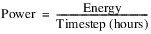
If energy is zero, Plant Efficiency and the Power Coefficient are also zero. Otherwise they are calculated as follows:
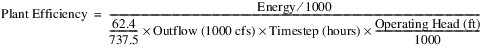
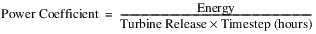
This method uses a three-dimensional table that contains the columns Operating Head, Turbine Release, and Power for each unit in the plant.
Slots Specific to This Method
Note: Many of these slots have column or row dimensions based on the number of units. The rows/columns of these slots are expanded at the beginning of the run to match the value in the Number of Units slot. When first configuring this method, the user must enter the Number of Units, then run the model (stepping through one timestep is enough) to grow the slots to the right dimensions. You are also able to edit the block size to match the number of units.
Auto Unit Best Turbine Q Table
Type: Table Slot
Units: Length, flow
Description: Table showing most efficient release levels for given operating heads
Information: This table is regenerated at the start of each run from the Unit Power Table. The first column for each block is Operating Head and second column is Turbine Release. It will have one block for each unit.
I/O: Automatically generated at beginning of run
Links: Not Linkable
Auto Unit Max Turbine Q Table
Type: Table Slot
Units: Length, Flow
Description: Table showing maximum release possible for given operating heads
Information: This table is regenerated at the start of each run from the Unit Power Table. The first column for each block is Operating Head and the second is Turbine Release. It will have one block for each unit.
I/O: Automatically generated
Links: Not Linkable
Minimum Power Elevation
Type: Table Slot
Units: Length
Description: The minimum elevation at which the reservoir can still produce power.
Information:
I/O: Optional Input Only
Links: Not Linkable
Number of Units
Type: Table Slot
Units: None
Description: Number of units in the plant
Information: This key scalar slot (existing slot, 1x1 table) indicates the number of units (turbines) at a power reservoir. The dimensions of several other slots are directly related to this value; specifically, both input data represented in Table Slots and unit-level series data represented in Agg Series Slots are require one row or column for each unit. At the beginning of each run, RiverWare will confirm that the value for the Number of Units slots is consistent with the dimensions of related slots. If any inconsistencies are detected, the relevant slots are grown as appropriate. If additional input data are required, the user is notified and the run is terminated.
I/O: Required Input only
Links: NA
Number of Units Generating
Type: Series Slot
Units: None
Description: Number of units that are generating at a given timestep
Information: The value is the sum of the Unit Is Generating
I/O: Output only
Links: NA
Power Curvature Tolerance
Type: Scalar Slot
Units: None
Description: The power curvature tolerance is used to account for anomalies in Unit Power Table data and round off error while calculating slopes.
Information: Although the units for the slot are None, the comparison is implicitly using (MW/cms)
I/O: Input or defaults to 1X10⁻⁶
Links: Links: Not linkable
Unit Is Generating
Type: Agg Series Slot
Units: None
Description: This slot is used to control whether units are available.
Information: There is one column for each unit. Before a run, an input value of 1 indicates that the unit must generate power at that date; otherwise an input value of 0 indicates that the unit cannot generate power at that timestep. A NaN indicates that the unit is available and the model will decide if it can generate. At the end of a run, an output of 1 indicates the unit generated power; 0 indicates it did not.
I/O: Input, Rules, or Output
Links: Not Linkable
Unit Energy
Type: Agg Series Slot
Units: Energy
Description: Energy produced by each unit
Information: There is one column for each unit. A value indicates the energy being generated by the unit at that timestep, and takes into account frequency regulation. A negative value can be input or set by a rule to represent a unit that is spinning, motoring, or condensing (actually consuming energy). You cannot specify (input or rules) both Unit Energy and Unit Turbine Release on the same timestep.
I/O: Input, Rules, or Output
Links: Not linkable
Unit Power
Type: Agg Series Slot
Units: Power
Description: The power that is generated by each unit
Information: There will be one column for each unit. A value indicates the power being generated by the unit at that timestep, and takes into account losses due to frequency regulation.
I/O: Output only
Links: Not linkable
Unit Power Table
Type: Table Slot
Units: Length, Flow, Power, Flow, Power, and so on
Description: A three-dimensional table relating operating head, turbine release, and power for each unit in the plant. There will be 1 block (3 columns) for each unit.
Information: The last row for each operating head represents the max capacity. Best efficiency is automatically calculated. The three values in a given row and unit block represent a legal operating point for that unit; that is, the Power which that unit would generate at that head and turbine flow. A point of zero flow and zero power production must be entered in the table for each operating head. It is also required that this table be concave. You can set the number of blocks on this table using the menus or start a run to grow this table based on the Number of Units. NaNs are allowed at the bottom of a block of data if another unit has more rows.
I/O: Required Input only
Links: NA
Unit 1 | Unit 2 | ||||
|---|---|---|---|---|---|
Operating Head (ft) | Turbine Flow (1000 cfs) | Power (KW) | Operating Head (ft) | Turbine Flow (1000 cfs) | Power (KW) |
100 | 0 | 0 | 99 | 0 | 0 |
100 | 10 | 2000 | 99 | 10 | 1000 |
100 | 20 | 3000 | 99 | 20 | 2000 |
100 | 30 | 4000 | 99 | 30 | 3000 |
200 | 0 | 0 | 200 | 0 | 0 |
200 | 10 | 2500 | 200 | 10 | 1700 |
200 | 20 | 3500 | 200 | 20 | 2500 |
200 | 25 | 3800 | 200 | 25 | 2800 |
200 | 30 | 4500 | 200 | 30 | 3500 |
300 | 0 | 0 | 295 | 0 | 0 |
300 | 10 | 3000 | 295 | 10 | 3000 |
300 | 25 | 5000 | 295 | 25 | 4000 |
Unit Priority Table
Type: Table Slot
Units: No Units
Description: The priority that each unit is started or stopped in the power plant
There will be one row for each unit. In optimization only, units with lower numerical values are higher priority and are scheduled to release power in preference to lower priority units. If a value is absent then that unit is given the lowest priority.
Currently, this table is only used in optimization. It is not used in simulation.
Note: Currently, units with equal priority are turned on/off in an arbitrary order. In the future, for units with equal priority, the unit efficiency will determine precedence; that is, a unit with a higher efficiency will be prioritized higher than other units with the same priority value.
I/O: Optional Input
Links: NA
Unit Turbine Release
Type: Agg Series Slot
Units: Flow
Description: Flow through each unit (turbine)
Information: There is one column for each unit. The value is the expected Turbine Release through the unit at that timestep. You cannot specify (input or rules) both Unit Energy and Unit Turbine Release on the same timestep.
I/O: Input, Rules, or Output
Links: Not Linkable
Using This Method for Simulation and Rulebased Simulation
When using the Unit Power Table method, you cannot specify (input or rules) the total Outflow, Energy, or Turbine Release slots. There are three approaches available for this method: specify Unit Turbine Release values, specify Unit Energy values, set the Max or Best flag on Energy. Each is described below.
Specify Unit Turbine Release Values
With this approach, you must specify (input or rules) the Unit Turbine Release for every unit. Then you must set the “U” flag (Unit Values) on the Turbine Release slot. (See Flags on the Timestep I/O Menu in User Interface for details on setting the “U” flag interactively from a slot dialog. See Buttons for Setting Flags on Slots in RiverWare Policy Language (RPL) for details about using the RPL Palette to set the “U” flag from a slot assignment in a rule.)
The “U” flag on Turbine Release will trigger the reservoir object to dispatch given Turbine Release, and it will indicate to the object to get the sum of the Unit Turbine Release values in order to set Turbine Release. When the reservoir object solves, it will calculate Unit Energy, total Turbine Release and total Energy.
Specify Unit Energy Values
With this approach, you must specify (input or rules) the Unit Energy for every unit. Then you must set the “U” flag (Unit Values) on the Energy slot. (See Flags on the Timestep I/O Menu in User Interface for details on setting the “U” flag interactively from a slot dialog. See Buttons for Setting Flags on Slots in RiverWare Policy Language (RPL) for details about using the RPL Palette to set the “U” flag from a slot assignment in a rule.)
The “U” flag on Energy will trigger the reservoir object to dispatch given Energy, and it will indicate to the object to get the sum of the Unit Energy values in order to set Energy.When the reservoir object solves, it will calculate Unit Turbine Release, total Turbine Release and total Energy.
Note: You must select the Unit Power Table Release method in the Power Release category if you specify Unit Energy values.
Max or Best Flag on Energy
• With this approach you set the “M” flag (Max Capacity) or “B” flag (Best Efficiency) on the Energy slot. No Unit Energy nor Unit Turbine Release values can be specified (input or rules). In the Unit Is Generating slot, you can specify a 0 for any that should not be used; that is, the unit is off line or otherwise unavailable.
• The M or “B” flag will trigger the reservoir object to solve given Energy, and it will calculate Unit Turbine Release, Unit Energy, total Turbine Release and total Energy, all of which will be either at maximum capacity or the best efficiency point, depending on which flag is used.
Note: You must select the Unit Power Table Release method in the Power Release category if you set the M or “B” flag on Energy.
Method Details
This method will use table interpolation to calculate Power and Energy at a known Operating Head based on the characteristics of each unit. This method, Unit Power Table, works in a similar manner to the current method, Plant Efficiency Curve.
At the beginning of the run, the method recreates the Auto Unit Best and Auto Unit Max Turbine Q tables from the Unit Power Table. The Auto Unit Max Turbine Q table are the points from the Unit Power Table that correspond to the largest Turbine Release for a given Operating Head. The Auto Unit Best Turbine Q table is calculated from the Unit Power Table as follows: For each unit and each operating head, the method determines the point (flow, power) that corresponds to a line drawn from the origin and it tangent to the curve. This tangent point is determined by calculating the slope of the line from each point to the origin; the point with the largest slope is the tangent. Then the operating head and turbine flow for this point are added to the Auto Unit Best Turbine Q.
Figure 30.1
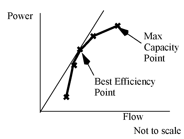
The description of the solution in this section assumes that mass balance has already occurred—that is, Inflow, Outflow, Storage, Pool Elevation have been calculated—and the method is trying to compute the Energy and Power produced by that Outflow. At the start of this method, there is also an estimate of the Turbine Release calculated as

where the spills are either known or estimated based on the current Pool Elevation. This Turbine Release may be reset if it cannot be met. If Energy is input, set by a rule, or flagged BEST EFFICIENCY (B) or MAX CAPACITY (M) or UNIT (U) then Energy and Power are solved using the method Unit Power Table Release; see Unit Power Table Release for details.
In this description, “t” indicates the current timestep and “u” indicates that the method will do this for each unit.
The method calculates the tailwater and operating head using the selected method and current release and pool elevation.
For each unit, the previous pool elevation will be compared to the unit’s minimum power elevation.
if (Pool Elevation[t-1] < Unit Minimum Power Elevation[u])
{
{
Either set the following to zero or make sure that they are zero:
Unit Turbine Release[t,u],
Unit Energy[t,u],
Unit Power[t,u], and
Unit is Generating[t,u].
If any of these are non-zero, an error is issued.
}
}
Next, the selected method in the Power Plant Failure category is executed. This method sets the Power Plant Cap Fraction (the default is 1.0) and checks for plant shutoff/failure.
Then, the method checks if the plant has shut off or failed (from the call to the selected Power Plant Failure category method), the following steps are taken.
1. Power, Energy, and Turbine Release are set equal to zero.
2. Either set the following to zero or make sure that they are zero:
– Unit Turbine Release[t,u],
– Unit Energy[t,u],
– Unit Power[t,u], and
– Unit is Generating[t,u].
If any of these are non-zero, an error is issued No further computations are performed.
Next for each unit, an estimate of max flow through all the turbines is calculated as follows: estimate a temporary variable maxPowerRelease (flow) using the Auto Unit Max Turbine Q table. This table contains the columns Operating Head and Turbine Capacity. Because Operating Head is known at the current timestep, table interpolation is used to calculate maxPowerRelease for the given average Operating Head.
If Outflow is set to “Max Capacity” flag, set the Unit Turbine Release to the maximum calculated and compute the power produced by those flows.
Otherwise, if Unit Turbine Release is input/rules for any of the units:
• If Unit is Generating is set (input/rules) to 0 for a unit that has a Unit Turbine release, issue an error.
• If Unit is Generating is set (input/rules) to 1 for a unit that does not have a Unit Turbine release, issue an error.
• If Turbine Release is not set by the “U” flag, check if Turbine Release =  Unit Turbine Release[u]. If they do not match and Turbine Release is input/rules, issue an error. Otherwise, if they do not match, the method resets Turbine Release equal to
  Unit Turbine Release[u].
Unit Turbine Release[u]. If they do not match and Turbine Release is input/rules, issue an error. Otherwise, if they do not match, the method resets Turbine Release equal to Unit Turbine Release[u].• If Turbine Release does have the “U” flag, the Turbine Release is set equal to  Unit Turbine Release[u].
Unit Turbine Release[u].• If Turbine Release is now greater than  maxPowerRelease[u], an error is issued as the specified unit turbine releases cannot be met.
maxPowerRelease[u], an error is issued as the specified unit turbine releases cannot be met. • If a regulation method is selected, call it here, otherwise, given the known Unit Turbine Releases[u], the method then looks up the unit flow and operating head on the Unit Power Table to determine the power produced by each unit: Unit Power[u].
• Finally, Unit Energy[u] = Unit Power[u] * Time (hrs)
• The total Power =  Unit Power[u] and total Energy =
  Unit Energy [u]
Unit Power[u] and total Energy = Unit Energy [u]• Else Unit Turbine Release is not input/rules
• Exit the method as there is no way to compute energy/power at a unit level. The dispatch method will continue but no power related slots (for example, Energy, Unit Energy, Power, Unit Power, Unit Turbine Release, Unit Is Generating, Unit Startup, Unit Shutdown, and so on) will be set. Turbine Release is set to the minimum of (Outflow - Spill or MaxPowerRelease). This can happen when dispatching given Inflow and Pool Elevation or Storage. and no Turbine Release or Unit Turbine Release is specified.
Finally, the method computes the slot Unit is Generating based on the Unit Turbine Release and Unit Energy. For each unit, if these are non zero, the Unit is Generating is set to 1. If they are zero, Unit is Generating is set to 0. No inputs are overwritten. Then, the Number of Units Generating is computed as the sum over the columns of the Unit is Generating slot.
Revised: 07/05/2022