
Local Inflow Spatial Disaggregation
The Local Inflow Spatial Disaggregation category contains three methods: the default, no action method, None, the WAM Precipitation Curve Number method, and the Drainage Area method. Both the WAM Precipitation Curve Number method and the Drainage method take known gage flows and estimate the flow at intervening or upstream Ungaged Control Points. The WAM Precipitation Curve Number method calculates an equivalent precipitation, using an empirical equation to relate watershed parameters, gage flows and precipitation. The Drainage Area method calculates a ratio between incremental gage drainage area and the ungaged drainage area to distribute flows. Spatial disaggregation is calculated at the start of the run for all enabled subbasins.
The three categories of disaggregation methods are executed in the following order:
1. Local Inflow Spatial Disaggregation
2. Local Inflow Temporal Disaggregation
3. Incremental Local Inflows. This category may include forecasting.
The computational subbasin executes the disaggregation methods at the beginning of a run and subsequently sets the relevant disaggregated local inflow slots as inputs on control points and reservoirs. In practice, users can run the model once to perform the disaggregation, then disable the subbasins related to disaggregation and save the model. When this method is used, future model runs will not execute the disaggregation methods and users will avoid the computational expense of disaggregating the local inflows at the beginning of each run. Should users want to recalculate their disaggregation methods, they should re-enable the subbasins and start a model run.
While the actual computation of the disaggregation occurs via the three methods on the computational subbasin, the data for the disaggregation is stored in method dependent slots on control points and reservoirs.
This method is the default for the Local Inflow Spatial Disaggregation category and should be selected when spatial disaggregation of local inflows is not desired.
There are no slots specific to this method.
This method computes the Distributed Flow values for all Ungaged Control Points in the subbasin given the known Distributed Flow values of the downstream Gage Control Point, upstream Gage Control Points (if any), and excluded Gage Control Points (if any).
There are no slots specific to this method.
The relevant data is held in method-dependent slots on the control points and is accessed by the computational subbasin. See WAM Precipitation Curve Number for details on these slots and the Local Inflow Spatial Disaggregation on Subbasin method on the Control Point.
The WAM Precipitation Curve Number method disaggregates using methods found in the Water Availability Model (WAM) developed by Dr. Ralph Wurbs at Texas A&M University. The WAM Precipitation Curve Number method is executed on the computational subbasin at the beginning of run if the subbasin is enabled. The method calculates the Distributed Flow at each ungaged control point using the NRCS curve number, mean precipitation, and drainage area of both the gaged and ungaged control points.
The downstream Gage Control Point calculates the gain in the basin, using the difference in Distributed Flow between the downstream gage control point and its upstream gage control point(s) as defined in the downstream gage. The effect of excluded gages is defined below.
The downstream Gage Control Point calculates the area of the basin, subtracting the area of all upstream gages from the area provided in the downstream gage. The upstream gage curve number and upstream gage mean precipitation are scaled by area and subtracted from the downstream gage curve number and mean precipitation, also scaled by area. The resulting curve number and mean precipitation are scaled by 1/area to calculate the updated curve number and mean precipitation.
Excluded gages may be defined in the Ungaged Control Point, to change the gain calculation for its downstream gage control point. For most basins, the Excluded gages list is not needed. Each Ungaged Control Point maintains its own list of excluded gages. When a gage is placed in the list, the downstream gage ignores that excluded gage when solving the gain, curve number, and mean precipitation at the downstream control point.
Method Details
The algorithm is described in the following steps.
1. All of the Ungaged Control Points in the computational subbasin are visited to perform the spatial disaggregation of flows to Ungaged Control Points. For each Ungaged Control Point to be calculated, the Downstream Gage is visited, and the incremental flow for that gage is calculated. Distributed Flow from upstream gages is subtracted from the Distributed Flow in the currently computed gage. Any upstream gages that are not tributary to the ungaged point may be left in the gage (not subtracted) using Excluded Gages list. This list may be different for each Ungaged Control Point, based on its location in the subbasin. The resulting set of incremental flows is only used for calculations pertaining to the current Ungaged Control Point.
2. The drainage areas are checked. An error occurs if the total drainage area of the Upstream Gage Control Points are equal or larger than the drainage area of the Downstream Gage Control Point or the Ungaged Control Point.
3. Incremental drainage area at the Downstream Gage Control Point is calculated, subtracting the sum of the drainage area for all Upstream Gage Control Points, except for those specified in the Excluded Gage Control Points list.
4. The incremental curve number at the Downstream Gage Control Point is calculated. The curve number is area weighted, subtracting the area weighted curve numbers from Upstream Gage Control Points, except for those specified in the Excluded Gage Control Points list.
5. The incremental mean precipitation at the downstream gage is calculated. The mean precipitation is area weighted, subtracting the area weighted mean precipitation from Upstream Gage Control Points, except for those specified in the Excluded Gage Control Points list.
6. Incremental drainage area at the Ungaged Control Point is calculated, subtracting the sum of the Drainage Area for all Upstream Gage Control Points.
7. The incremental curve number at the Ungaged Control Point is calculated. The Curve Number is area weighted, subtracting the area weighted curve numbers from Upstream Gage Control Points.
8. The incremental mean precipitation at the Ungaged Control Point is calculated. The mean precipitation is area weighted, subtracting the area weighted mean precipitation from Upstream Gage Control Points.
9. The incremental runoff (Q) at the Downstream Gage Control Point is computed by dividing the monthly incremental inflow at the Downstream Gage Control Point by its incremental drainage area.
10. The precipitation depth (P) at the Downstream Gage Control Point is calculated through an iterative solution (bisection) given the runoff computed in the previous step and the value of S as follows.


11. If the Downstream Gage Control Point runoff (Q) is less than or equal to zero, the precipitation depth (P) at the Downstream Gage Control Point is 0.2 times the value of S.
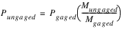
12. The precipitation depth at the Ungaged Control Point is computed by adjusting the precipitation depth at the Downstream Gage Control Point by the ratio of the mean precipitation depth (M) at the ungaged and gaged control points.
13. In order to avoid a divide by zero error and the better match reality, the Downstream Gage Control Point’s mean precipitation depth must be greater than zero. For consistency, the Ungaged Control Point’s mean precipitation depth must also be greater than zero.
14. The runoff at the Ungaged Control Point is then computed using curve number equation using Pungaged and Sungaged for the Ungaged Control Point.
15. The computed value for the runoff is then converted to incremental streamflow. Incremental streamflow is added to the Upstream Gage Control Point streamflow to calculate an initial estimate of streamflow at the Ungaged Control Point.
16. The initial estimate is compared to the downstream gage flow, and the minimum is selected. The results at the upstream gage point never exceed the downstream gage flows.
17. Set the results to the Distributed Flow slot as inputs.
The iterative solution for Precipitation in Step 10 is solved using the bisection method. The bisection routine is an incremental search method in which the function is reevaluated at the midpoint of the interval between the values of the previous two guesses to determine on which side of the midpoint the root lies. Depending on which side of the midpoint the root lies, the midpoint becomes either the upper or lower bound to the search interval. The interval is again divided in half and the function is reevaluated at the midpoint. This procedure is repeated until the solution is obtained. The bisection method typically uses the maximum and minimum values for the unknown variable and finds the midpoint of these to use as the seed value to start the iteration. While the minimum value of Precipitation is zero, the maximum value is not clearly defined at the start of step 10, thus a seed value of P = Mean Precipitation will be used to start the bisection routine. If the right hand side (RHS) of the equation in step 10 is smaller than the runoff (the left hand side (LHS) of the equation) the value of P will become twice the previous value for P (that is, twice the Mean Precipitation). This will be repeated until the RHS is larger than the LHS, indicating that an upper bound for P has been determined. From here the bisection method continues in the usual fashion. If the seed value of P results in the RHS of the equation in step 10 being larger than LHS, the value of P will become 0.5 times Mean Precipitation (that is, the midpoint between the minimum value, 0, and the initial value, Mean Precipitation). From here the bisection method proceeds in the typical fashion. The bisection method will continue until two successive solutions are within convergence of each other or until maximum iterations is reached. Convergence is defined as the convergence criteria set on the gage control point’s Distributed Flow slot.
Note: The empirical equations in this method use units of acres for drainage area, acre-feet per month for flow, inches per month for runoff and inches for precipitation. Curve Number is unitless. Users can enter data in any units and the values will be internally converted for the computation.
The method will set the non-gage control points’ Distributed Flow slots as input to avoid these values being cleared in subsequent model runs. After the WAM Precipitation Curve Number is completed, all control points will contain a value in the Distributed Flow slot for all timesteps in the slot. After the WAM Precipitation Curve Number method is completed, data is made available for the next stage of the disaggregation or forecast depending on which is the next selected method.
Note: All steps of the disaggregation and forecast will be taken in sequence: the local inflow spatial disaggregation (if any) occurs first, the local inflow temporal disaggregation (if any) occurs next, and then the calculation of incremental values (if any).
If a non-none Local Inflow Temporal Disaggregation method is the next selected method, the Distributed Flow values will be used in the temporal disaggregation calculations. If the Compute Incremental Local Inflows method is the next selected method, Distributed Flow values are copied into the Cumulative Local Inflow slot for the computation of incremental flows, but only if the timestep sizes of the two slots match. If no other disaggregation or forecast method is selected, the Disaggregated Flow slot is copied into the Local Inflow slot. This copying of slots occurs during beginning of run.
The default timestep size for the Distributed Flow and Mean Precipitation slots is months. This can, however, be changed by the user by configuring the timeseries and is independent from the model timestep size. It is up to the user to make sure the timestep size and associated data are appropriate.
Model Setup
The computational subbasin must be set up for each subbasin in which flows will be spatially disaggregated. On the computational subbasin, select WAM Precipitation Curve Number method from the Local Inflow Spatial Disaggregation category. Append the relevant control points to the subbasin. Each spatial disaggregation subbasin should include at least one Ungaged Control Point, where flow will be determined using the Gage Control Point(s) as a reference. Each Ungaged Control Point should be included in only one subbasin.
For each control point in the computational subbasin, the WAM Precipitation Curve Number method must be selected from the Local Inflow Spatial Disaggregation category. Selecting the WAM Precipitation Curve Number method enables the Gage Control Point category. Select the Gage Control Point method from the Gage Control Point category for each gage control point in the basin.
Note: Upstream control points do not need to be a member of this subbasin, but they need to be a member of at least one subbasin.
All other control points should have None selected in the Gage Control Point category. If necessary, change the timestep size of the Distributed Flow and Mean Precipitation slots (default is 1 Month). Input data into the Drainage Area, Curve Number, and Mean Precipitation slots on all control points and the Distributed Flow slot on the gage control point.
This method computes the Distributed Flow values for all non-gage control points in the subbasin given the known Distributed Flow values of the Gage Control Point.
There are no slots specific to this method.
The relevant data is held in method-dependent slots on the control points and is accessed by the computational subbasin. See Drainage Area for details on these slots and the Local Inflow Spatial Disaggregation on Subbasin method on the Control Point.
The Drainage Area method disaggregates using the drainage area ratio between the Ungaged Control Point and the downstream Gaged Control Point. The downstream Gage Control Point calculates the gain in the basin, using the difference in Distributed Flow between the downstream gage control point and its upstream gage control point(s) as defined in the downstream gage. Excluded gages can be defined in the Ungaged Control Point, to force the calculation to ignore the existence of that gage when solving the gain at the downstream control point.
The downstream Gage Control Point calculates the gain in the basin, using the difference in Distributed Flow between the downstream gage control point and its upstream gage control point(s) as defined in the downstream gage. The effect of excluded gages is defined below.
The downstream Gage Control Point calculates the area of the basin, subtracting the area of all upstream gages from the area provided in the downstream gage.
Excluded gages can be defined in the Ungaged Control Point, to change the gain calculation for its downstream gage control point. For most basins, the Excluded gages list is not needed. Each Ungaged Control Point maintains its own list of excluded gages. When a gage is placed in the list, the downstream gage ignores that excluded gage when solving the gain at the downstream control point.
Method Details
The algorithm is described in the following steps.
1. All of the Ungaged Control Points in the computational subbasin are visited. For each Ungaged Control Point to be calculated, the Downstream Gage is visited, and the incremental flow for that gage is calculated. Distributed Flow from upstream gages is subtracted from the Distributed Flow in the currently computed gage. Any upstream gages that are not tributary to the ungaged point can be left in the gage (not subtracted) using Excluded Gages list. This list may be different for each Ungaged Control Point, based on its location in the subbasin. This set of incremental flows is only used in the remaining calculations pertaining to the current Ungaged Control Point.
2. The drainage areas are checked. An error occurs if the total drainage area of the Upstream Gage Control Points are equal or larger than the drainage area of the Downstream Gage Control Point or the Ungaged Control Point.
3. Incremental drainage area at the Downstream Gage Control Point is calculated, subtracting the sum of the drainage area for all Upstream Gage Control Points tributary to the Ungaged Control Point.
4. Incremental drainage area at the Ungaged Control Point is calculated, subtracting the sum of the Drainage Area for all Upstream Gage Control Points.
5. The ratio of incremental drainage area of the Ungaged Control Point to the Gaged Control Point is used to scale the downstream gage incremental flows.
6. Any upstream gages that are tributary to the Ungaged Control Point are added to the result of step 5.
7. The results are stored as input in the Ungaged Control Point’s Distributed Flow slot.
Revised: 07/05/2022