
Diversion Power
The methods in this category calculate power generated on the diversion from the reservoir. Selecting a method other than None in this category will make the Diversion Tailwater and Diversion Power Bypass categories available. If a method other than None is selected for Diversion Power, then a method other than None must be selected for Diversion Tailwater.
This is the default method for the Diversion Power category. No calculations are performed in this method.
There are no slots specific to this method.
The Diversion Power Efficiency Curve method is similar to the Plant Efficiency Curve method in the Power category with the exception that the method does not allow Diversion Energy to input or set by rules (nor can Diversion Energy be set with the Best Efficiency or Max Capacity flags). Diversion Energy and Diversion Power are only calculated as outputs. The method calculates Diversion Power by a 3‑D interpolation of the Diversion Power Table using the current, average Diversion Operating Head and Diversion Turbine Flow. The Diversion Power Coefficient is calculated as Diversion Power divided by Diversion Turbine Flow. Alternatively, the user can input Diversion Power Coefficient, and then Diversion Power is calculated directly as the Diversion Power Coefficient multiplied by the Diversion Turbine Flow.
Slots Specific to This Method
Diversion Power Table
Type: Table Slot
Units: Length vs Flow vs Power
Description: 3‑D table representing the power characteristics of the diversion power plant, used to calculate power using interpolation
Information: Data must be entered into the table in increasing, blocks of the same Diversion Operating Head. For every block of the same Diversion Operating Head in column 1, Diversion Turbine Flow should be listed in increasing order in column 2 and the corresponding Diversion Power in column 3. The first row for each Diversion Operating Head must be for zero Diversion Turbine Flow and zero Diversion Power.
I/O: Required input
Links: Not linkable
Div Head | Turbine Flow | Div Power |
|---|---|---|
30 | 0 | 0 |
30 | 100 | 100 |
30 | 200 | 175 |
40 | 0 | 0 |
40 | 100 | 125 |
40 | 220 | 195 |
50 | 0 | 0 |
50 | 110 | 147 |
50 | 250 | 205 |
Diversion Max Turbine Table
Type: Table Slot
Units: Length vs Flow
Description: The maximum Diversion Turbine Flow as a function of Diversion Operating Head
Information: RiverWare automatically populates this table at the start of the run using the Diversion Power Table. The first column contains the Diversion Operating Head values from the Diversion Power Table, one row for each unique Diversion Operating Head in increasing order. The second column contains the maximum Diversion Turbine Flow value for each Diversion Operating Head.
I/O: Output only
Links: Not linkable
Diversion Power Cap Fraction
Type: Series Slot
Units: Fraction
Description: This is the percentage of full capacity of the turbine units in the diversion power plant. For example, if only half of the turbine are operational (and they are all the same), this value would be 0.5.
Information: This must be a number between 0 and 1 (inclusive). If not input or set by rules, this slot is automatically set to 1.
I/O: Optional input, if not, value is set to 1
Links: Not linkable
Diversion Operating Head
Type: Series Slot
Units: Length
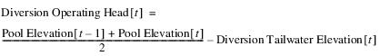
Description: The difference between the average Pool Elevation and the Diversion Tailwater Elevation
Information:
I/O: Output only
Links: Not usually linked
Diversion Turbine Flow
Type: Series Slot
Units: Flow
Description: The diversion flow that passes through the turbines to generate power
Information: If the slot is not input or set by rules, then it is calculated as the difference between Diversion and Diversion Power Bypass if Diversion Power Bypass is input or set by rules. If neither Diversion Turbine Flow nor Diversion Power Bypass is input or set by rules, then Diversion Turbine Flow is calculated as the lesser of Diversion and the calculated maximum diversion turbine flow based on the Diversion Max Turbine Table and the current Diversion Operating Head. It is not permissible to have both Diversion Turbine Flow and Diversion Power Bypass as input or set by rules.
I/O: Optional input or output
Links: Not linkable
Diversion Power
Type: Series Slot
Units: Power
Description: The power generated from flow through the reservoir diversion
Information: If Diversion Power Coefficient is not input or set by rules, Diversion Power is calculated using a 3‑D interpolation on the Diversion Power Table given the current, average Diversion Operating Head and the current Diversion Turbine Flow, scaled by the Diversion Power Cap Fraction. If Diversion Power Coefficient is input or set by rules, Diversion Power is calculated as the Diversion Power Coefficient multiplied by the Diversion Turbine Flow.
I/O: Output only
Links: Linkable
Diversion Energy
Type: Series Slot
Units: Energy
Description: The energy generated from flow through the reservoir diversion
Information: Calculated as the Diversion Power multiplied by the timestep length
I/O: Output only
Links: Linkable
Diversion Power Coefficient
Type: Series Slot
Units: Power per Flow
Description: The power generation per unit of flow through the turbines on the reservoir diversion
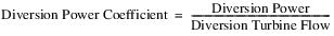
Information: If this slot is input or set by rules, it is used directly to calculate Diversion Power. If it is not input or set by rules, then it is calculated as Diversion Power divided by Diversion Turbine Flow. If either Diversion Power, Diversion Turbine Flow or Diversion Power Cap Fraction is zero, then this slot will be zero.
I/O: Optional input or output
Links: Not usually linked
Method Details
At the start of the run, the Diversion Max Turbine Table slot is populated using the Diversion Power Table. The first column is populated with each unique Diversion Operating Head value from the Diversion Power Table, in ascending order. The second column is populated with the corresponding maximum diversion turbine flow value.
When the method executes, Diversion will already be known. The method calls the selected Diversion Tailwater method to calculate the Diversion Tailwater Elevation. If the default method, None, is selected for the Diversion Tailwater category, the run terminates and an error message will be issued.
The method then calculates the Diversion Operating Head as follows:
The method calculates the maxDiversionTurbineFlow by interpolating the Diversion Max Turbine Table slot using the Diversion Operating Head. The value is scaled by the Diversion Power Cap Fraction.
If Diversion Turbine Flow is specified (input or set by rules) it is checked against the maxDiversionTurbineFlow, and if the specified value exceeds the max, the run terminates with an error message. Otherwise a temporary turbine flow is calculated.

If Diversion Power Bypass is not input or set by rules, or if the Diversion Power Bypass method is None, the Diversion Power Bypass will have defaulted to zero at this point.
If the combined temporary turbine flow plus the current Diversion Power Bypass is less than the (total) Diversion, then the method then calls the selected Diversion Power Bypass method to increase the Diversion Power Bypass to make up the difference. If it is not possible for the turbine flow plus the bypass to equal the total Diversion, either due to the values being specified (input or rules) or due to max capacity limits, then the run terminates with an error message.
The method then sets the Diversion Turbine Flow slot as follows:

If Diversion Power Coefficient is specified (input or rules), it is used to calculate Diversion Power directly, as follows:

Otherwise, Diversion Power is calculated by a 3‑D interpolation on the Diversion Power Table using Diversion Operating Head and Diversion Turbine Flow, and Diversion Power Coefficient is calculated as follows:
Diversion Energy is then calculated as Diversion Power multiplied by the timestep length.
Note: Regarding Diversion Power Cap Fraction: If the Diversion Power Cap Fraction is input by the user, it is necessary for the Diversion Power Table to be scaled back to account for the operating points when the turbines are operating at less than 100%. To do this, Diversion Turbine Flow is divided by the Diversion Power Cap Fraction. This point is then found in the Diversion Power Curve for the current Diversion Operating Head, and the power is found using 3‑D interpolation. Finally the power is multiplied by the Diversion Power Cap Fraction to get the actual Diversion Power produced for the current timestep.
Revised: 01/04/2021